TR-369 – The User Services Platform
Issue: 1 Amendment 5
Issue Date: January 2026
List of Figures
- USP Agent and Controller Architecture
- Receiving a X.509 Certificate
- Example: USP Request/Response over the CoAP MTP
- WebSocket Session Handshake
- USP Request using a WebSocket Session
- USP over STOMP Architecture
- USP over MQTT Architecture
- MQTT Packets
- Unix Domain Socket Binding
- UNIX Domain Socket Frame with Handshake Message
- UNIX Domain Socket Frame with Handshake Message
- UNIX Domain Socket Frame with USP Record Message
- Processing of Received USP Records
- E2E Segmentation and Reassembly
- TLS Session Handshake
- A successful request/response sequence
- A failed request/response sequence
- Operate Message Flow for Synchronous Operations
- Operate Message Flow for Asynchronous Operations
- Receiving a USP Record
- USP Record without USP Layer Secure Message Exchange
- Sending a USP Record
- Checking a Certificate
- Determining the Role
- Trusted Broker with Received Record
- Trusted Broker Sending a Record
- Deployment Unit State Diagram
- Execution Unit State Diagram
- Possible Multi-Execution Environment Implementation
- Execution Environment State Diagram
- Example of MTP Proxy in LAN with WAN Controller
- CoAP-STOMP MTP Proxy Example Flow
- IoT Data Model
- IoT individual device models
- IoT proxied device model
- IoT threshold trigger sensitivity
- IoT threshold trigger hold time
- IoT threshold trigger rest time
- IoT threshold trigger minimum duration
- Software Modularization Use Cases
List of Tables
Notice
The Broadband Forum is a non-profit corporation organized to create guidelines for broadband network system development and deployment. This Technical Report has been approved by members of the Forum. This Technical Report is subject to change. This Technical Report is owned and copyrighted by the Broadband Forum, and all rights are reserved. Portions of this Technical Report may be owned and/or copyrighted by Broadband Forum members.
Intellectual Property
Recipients of this Technical Report are requested to submit, with their comments, notification of any relevant patent claims or other intellectual property rights of which they may be aware that might be infringed by any implementation of this Technical Report, or use of any software code normatively referenced in this Technical Report, and to provide supporting documentation.
Terms of Use
1. License
Broadband Forum hereby grants you the right, without charge, on a perpetual, non-exclusive and worldwide basis, to utilize the Technical Report for the purpose of developing, making, having made, using, marketing, importing, offering to sell or license, and selling or licensing, and to otherwise distribute, products complying with the Technical Report, in all cases subject to the conditions set forth in this notice and any relevant patent and other intellectual property rights of third parties (which may include members of Broadband Forum). This license grant does not include the right to sublicense, modify or create derivative works based upon the Technical Report except to the extent this Technical Report includes text implementable in computer code, in which case your right under this License to create and modify derivative works is limited to modifying and creating derivative works of such code. For the avoidance of doubt, except as qualified by the preceding sentence, products implementing this Technical Report are not deemed to be derivative works of the Technical Report.
2. NO WARRANTIES
THIS TECHNICAL REPORT IS BEING OFFERED WITHOUT ANY WARRANTY WHATSOEVER, AND IN PARTICULAR, ANY WARRANTY OF NONINFRINGEMENT AND ANY IMPLIED WARRANTIES ARE EXPRESSLY DISCLAIMED. ANY USE OF THIS TECHNICAL REPORT SHALL BE MADE ENTIRELY AT THE USER’S OR IMPLEMENTER’S OWN RISK, AND NEITHER THE BROADBAND FORUM, NOR ANY OF ITS MEMBERS OR SUBMITTERS, SHALL HAVE ANY LIABILITY WHATSOEVER TO ANY USER, IMPLEMENTER, OR THIRD PARTY FOR ANY DAMAGES OF ANY NATURE WHATSOEVER, DIRECTLY OR INDIRECTLY, ARISING FROM THE USE OF THIS TECHNICAL REPORT, INCLUDING BUT NOT LIMITED TO, ANY CONSEQUENTIAL, SPECIAL, PUNITIVE, INCIDENTAL, AND INDIRECT DAMAGES.
3. THIRD PARTY RIGHTS
Without limiting the generality of Section 2 above, BROADBAND FORUM ASSUMES NO RESPONSIBILITY TO COMPILE, CONFIRM, UPDATE OR MAKE PUBLIC ANY THIRD PARTY ASSERTIONS OF PATENT OR OTHER INTELLECTUAL PROPERTY RIGHTS THAT MIGHT NOW OR IN THE FUTURE BE INFRINGED BY AN IMPLEMENTATION OF THE TECHNICAL REPORT IN ITS CURRENT, OR IN ANY FUTURE FORM. IF ANY SUCH RIGHTS ARE DESCRIBED ON THE TECHNICAL REPORT, BROADBAND FORUM TAKES NO POSITION AS TO THE VALIDITY OR INVALIDITY OF SUCH ASSERTIONS, OR THAT ALL SUCH ASSERTIONS THAT HAVE OR MAY BE MADE ARE SO LISTED.
All copies of this Technical Report (or any portion hereof) must include the notices, legends, and other provisions set forth on this page.
Issue History
| Issue Number | Approval Date | Changes |
|---|---|---|
April 2018 |
Release contains specification for the User Services Platform 1.0 Corresponds to TR-181 Issue 2 Amendment 12 |
|
| Release 1.0.1 | August 2018 |
|
| Release 1.0.2 | November 2018 |
|
October 2019 |
Release contains specification for the User Services Platform 1.1
Corresponds to TR-181 Issue 2 Amendment 13 |
|
| Release 1.1.1 | April 2020 | Regenerated data model HTML using fixed version of the BBF report tool |
| Release 1.1.2 | August 2020 | Clarifies several examples, requirements, and error types |
| Release 1.1.3 | November 2020 | Corresponds to TR-106 Amendment 10 and TR-181 Issue 2 Amendment 14 |
| Release 1.1.4 | November 2020 | Corresponds to TR-181 Issue 2 Amendment 14 Corrigendum 1 |
January 2022 |
Release contains specification for the User Services Platform 1.2
Corresponds to TR-106 Amendment 11 and TR-181 Issue 2 Amendment 15 |
|
June 2023 |
Release contains the specification for the User Services Platform 1.3
|
|
| Release 1.3.1 | October 2023 | This Corrigendum has the following fixes
|
July 2024 |
Release contains the specification for the User Services Platform 1.4
|
|
| Release 1.3.2 | March 2025 | This Corrigendum has the following fixes
|
June 2025 |
Release contains the specification for the User Services Platform 1.4.1
|
|
July 2025 |
Release contains the specification for the User Services Platform 1.4.2
|
|
January 2026 |
Release contains the specification for the User Services Platform 1.5
|
Comments or questions about this Broadband Forum Technical Report should be directed to info@broadband-forum.org.
Editors
| Name | Company | Role |
|---|---|---|
| Tim Spets | Nokia | Editor/USP Project Lead |
| Jason Walls | QA Cafe, LLC | Editor/Broadband User Services Work Area Director |
| John Blackford | Vantiva | Editor/Broadband User Services Work Area Director |
Acknowledgments
| Name | Company |
|---|---|
| Jean-Didier Ott | Orange |
| Timothy Carey | Nokia |
| Steven Nicolai | Arris |
| Apostolos Papageorgiou | NEC |
| Mark Tabry | |
| Klaus Wich | Huawei |
| Daniel Egger | Axiros |
| Bahadir Danisik | Nokia |
| William Lupton | Broadband Forum |
| Barbara Stark | AT&T |
1 Introduction
1.1 Executive Summary
This document describes the architecture, protocol, and data model that build an intelligent User Services Platform. It is targeted towards application developers, application service providers, vendors, consumer electronics manufacturers, and broadband and mobile network providers who want to expand the value of the end user’s network connection and their connected devices.
The term “connected device” is a broad one, applying to the vast array of network connected devices, consumer electronics, and computing resources that today’s consumers are using at an increasing rate. With the advent of “smart” platforms (phones, tablets, and wearables) plus the emerging Internet of Things, the number of connected devices the average user or household contains is growing by several orders of magnitude.
In addition, users of the fixed and mobile broadband network are hungry for advanced broadband and intelligent cloud services. As this desire increases, users are turning towards over-the-top providers to consume the security, entertainment, productivity, and storage applications they want.
These realities have created an opportunity for consumer electronics vendors, application developers, and broadband and mobile network providers. These connected devices and services need to be managed, monitored, troubleshot, and controlled in an easy to develop and interoperable way. A unified framework for these is attractive if we want to enable providers, developers, and vendors to create value for the end user. The goal should be to create a system for developing, deploying, and supporting these services for end users on the platform created by their connectivity and components, that is, to be able to treat the connected user herself as a platform for applications.
To address this opportunity, use cases supported by USP include:
- Management of IoT devices through re-usable data model objects.
- Allowing the user to interact with their devices and services using customer portals or control points on their own smart devices.
- The ability to deploy and manage containerized microservices for end-users via software modularization and USP-enabled applications.
- The ability to have both the application and network service provider manage, troubleshoot, and control different aspects of the services they are responsible for, and enabling provider partnerships.
- Providing a consistent user experience from mobile to home.
- Simple migration from the CPE WAN Management Protocol [1] (CWMP) – commonly known by its document number, “TR-069” – through use of the same data model and data modeling tools.
1.2 Purpose and Scope
1.2.1 Purpose
This document provides the normative requirements and operational description of the User Services Platform (USP). USP is designed for consumer electronics/IoT, home network/gateways, smart Wi-Fi systems, and deploying and managing other value-added services and applications. It is targeted towards developers, application providers, and network service providers looking to deploy those products.
1.2.2 Scope
This document identifies the USP:
- Architecture
- Data model interaction
- Record structure, syntax, and rules
- Message structure, syntax, and rules
- Bindings that allow specific protocols to carry USP Records in their payloads
- Discovery and advertisement mechanisms
- Extensions for proxying, software module management, device modularization, firmware lifecycle management, bulk data collection, device-agent association, and an IoT theory of operations.
- Security credentials and logic
- Encryption mechanisms
Lastly, USP makes use of and expands the Device:2 Data Model [3]. While particular Objects and Parameters necessary to the function of USP are mentioned here, their normative description can be found in that document.
1.3 References and Terminology
1.3.1 Conventions
In this specification, several words are used to signify the requirements of the specification. These words are always capitalized. More information can be found in RFC 2119 [9] for key words defined there. Additional key words defined in the context of this specification are DEPRECATED and OBSOLETED.
MUST
This word, or the term “REQUIRED”, means that the definition is an absolute requirement of the specification.
MUST NOT
This phrase means that the definition is an absolute prohibition of the specification.
SHOULD
This word, or the term “RECOMMENDED”, means that there could exist valid reasons in particular circumstances to ignore this item, but the full implications need to be understood and carefully weighed before choosing a different course.
SHOULD NOT
This phrase, or the phrase “NOT RECOMMENDED” means that there could exist valid reasons in particular circumstances when the particular behavior is acceptable or even useful, but the full implications need to be understood and the case carefully weighed before implementing any behavior described with this label.
MAY
This word, or the term “OPTIONAL”, means that this item is one of an allowed set of alternatives. An implementation that does not include this option MUST be prepared to inter-operate with another implementation that does include the option.
DEPRECATED
This word refers to a requirement or section of this specification that is defined and valid in the current version of this specification but is not strictly necessary. This may be done for various reasons, such as irreparable problems being discovered or another more useful method being defined to accomplish the same purpose. When this word is applied to a requirement, it takes precedence over any normative language in the DEPRECATED requirement. DEPRECATED requirements SHOULD NOT be implemented. When this word is used on a section, it means the entirety of the section SHOULD NOT be implemented – but if it is implemented the requirements in the section are to be implemented as written. Note that DEPRECATED requirements and sections might be removed from the next major version of this specification.
OBSOLETED
This word refers to a requirement or section of this specification that meets the definition of DEPRECATED, but which has also been declared obsolete. Such requirements or entire sections MUST NOT be implemented; they might be removed from a later minor version of this specification.
1.3.2 References
The following references are of relevance to this Technical Report. At the time of publication, the editions indicated were valid. All references are subject to revision; users of this Technical Report are therefore encouraged to investigate the possibility of applying the most recent edition of the references listed below.
A list of currently valid Broadband Forum Technical Reports is published at www.broadband-forum.org.
1.4 Definitions
The following terminology is used throughout this specification.
Absolute Time
Time maintained by the Device that is synchronized with a trusted external time source, such as an NTP server or a real-time clock.
Agent
An Agent is an Endpoint that exposes Service Elements to one or more Controllers.
Binding
A Binding is a means of sending Messages across an underlying Message Transfer Protocol.
Command
The term used to define and refer to an Object-specific Operation in the Agent’s Instantiated or Supported Data Model.
Command Path
A Command Path is a Path Name that addresses a Command of an Object or Object Instance. See Path Names.
Connection Capabilities
Connection Capabilities are information related to an Endpoint that describe how to communicate with that Endpoint, and provide a very basic idea of what sort of function the Endpoint serves.
Controller
A Controller is an Endpoint that manipulates Service Elements through one or more Agents.
Discovery
Discovery is the process by which Controllers become aware of Agents and Agents become aware of Controllers.
Endpoint
An Endpoint is a termination point for a Message.
Endpoint Identifier
The Endpoint Identifier is a globally unique USP layer identifier of an Endpoint.
End to End Message Exchange
USP feature that allows for message integrity protection through the creation of a session context.
Error
An Error is a Message that contains failure information associated with a Request.
Event
An Event is a set of conditions that, when met, triggers the sending of a Notification.
Event Path
A Event Path is a Path Name that addresses an Event of an Object or Object Instance. See Path Names.
Expression
See also Search Expression.
Expression Component
An Expression Component is the part of a Search Expression that gives the matching Parameter criteria for the search. It consists of an Expression Parameter followed by an Expression Operator followed by an Expression Constant.
Expression Constant
The Expression Constant is the value used to compare against the Expression Component to determine if a search matches a given Object.
Expression Operator
The Expression Operator is the operator used to determine how the Expression Component will be evaluated against the Expression Constant, i.e., equals (==), not equals (!=), contains (~=), less than (<), greater than (>), less than or equal (<=) and greater than or equal (>=).
Expression Parameter
The Expression Parameter is a Parameter relative to the Path Name where an Expression Variable occurs that will be used with the Expression Constant to evaluate the Expression Component.
Expression Variable
The Expression Variable is an identifier used to allow relative addressing when building an Expression Component.
Instantiated Data Model
The Instantiated Data Model of an Agent represents the current set of Service Elements (and their state) that are exposed to one or more Controllers.
Instance Identifier
A term used to identify an Instance of a Multi-Instance Object (also called a Row of a Table). While all Multi-Instance Objects have an Instance Number that can be used as an Instance Identifier, an Object Instance can also be referenced using any of that Object’s Unique Keys.
Instance Number
An Instance Number is a numeric Instance Identifier assigned by the Agent to instances of Multi-Instance Objects in an Agent’s Instantiated Data Model.
Message
A Message refers to the contents of a USP layer communication including exactly one Message Header and exactly one Message Body.
Message Body
The Message Body is the portion of a Message that contains one of the following: Request, Response, or Error.
Message Header
The portion of a Message that contains elements that provide information about the Message, including the Message type, and Message ID elements.
Message ID
A Message ID is an identifier used to associate a Response or Error with a Request.
Message Transfer Protocol
A Message Transfer Protocol (MTP) is the protocol at a layer below USP that carries a Message, e.g., WebSocket.
Multi-Instance Object
A Multi-Instance Object refers to an Object that can be created or deleted in the Agent’s Instantiated Data Model. Also called a Table.
Notification
A Notification is a Request from an Agent that conveys information about an Event to a Controller that has a Subscription to that event.
Object
An Object refers to a defined type that an Agent represents and exposes. A Service Element may be comprised of one or more Objects and Sub-Objects.
Object Instance
An Object Instance refers to a single instance Object of a type defined by a Multi-Instance Object in the Agent’s Instantiated Data Model. Also called a Row of a Table.
Object Instance Path
An Object Instance Path is a Path Name that addresses an Instance of a Multi-Instance Object (also called a Row of a Table). It includes the Object Path followed by an Instance Identifier. See Path Names.
Object Path
An Object Path is a Path Name that addresses an Object. In the case of Multi-Instance Objects, an Object Path addresses the Object type itself rather than instances of that Object, which are addressed by Object Instance Paths. See Path Names.
Operation
A method defined for a particular Service Element that can be invoked with the Operate Message.
Parameter
A Parameter is a variable or attribute of an Object. Parameters have both type and value.
Parameter Path
A Parameter Path is a Path Name that addresses a Parameter of an Object or Object Instance. See Path Names.
Path Name
A Path Name is a fully qualified reference to an Object, Object Instance, Command, Event, or Parameter in an Agent’s Instantiated or Supported Data Model. See Path Names.
Path Reference
A Path Reference is a Parameter data type that contains a Path Name to an Object or Parameter that may be automatically followed by using certain Path Name syntax.
Record
The Record is defined as the Message Transfer Protocol (MTP) payload, encapsulating a sequence of datagrams that consists of the Message as well as essential protocol information such as the USP version, the source Endpoint ID, and the target Endpoint ID. It can also contain additional metadata needed for providing integrity protection, payload protection and delivery of fragmented Messages.
Register
To Register means to use the Register message to inform a Controller of Service Elements that this Agent represents.
Registered
Registered Service Elements are those elements represented by an Agent that have been the subject of a Register message.
Relative Path
A Relative Path is the remaining Path Name information necessary to form a Path Name given a parent Object Path. It is used for message efficiency when addressing Path Names.
Request
A Request is a type of Message that either requests the Agent perform some action (create, update, delete, operate, etc.), requests information about an Agent or one or more Service Elements, or acts as a means to deliver Notifications and Register Messages from the Agent to the Controller. A Request usually requires a Response.
Response
A Response is a type of Message that provides return information about the successful processing of a Request.
Role
A Role refers to the set of permissions (i.e., an access control list) that a Controller is granted by an Agent to interact with objects in its Instantiated Data Model.
Row
The term Row refers to an Instance of a Multi-Instance Object in the Agent’s Instantiated Data Model.
Search Expression
A Search Expression is used in a Search Path to apply specified search criteria to address a set of Multi-Instance Objects and/or their Parameters.
Search Path
A Search Path is a Path Name that contains search criteria for addressing a set of Multi-Instance Objects and/or their Parameters. A Search Path may contain a Search Expression or Wildcard.
Service Element
A Service Element represents a piece of service functionality that is exposed by an Agent, usually represented by one or more Objects.
Source Endpoint
The Endpoint that was the sender of a message.
Subscription
A Subscription is a set of logic that tells an Agent which Notifications to send to a particular Controller.
Supported Data Model
The Supported Data Model of an Agent represents the complete set of Service Elements it is capable of exposing to a Controller. It is defined by the union of all the Device Type Definitions the Agent exposes to the Controller.
Table
The term Table refers to a Multi-Instance Object in an Agent’s Instantiated or Supported Data Model.
Target Endpoint
The Endpoint that was the intended receiver of a message.
Trusted Broker
An intermediary that either (1) ensures the Endpoint ID in all
brokered Endpoint’s USP Record from_id matches the Endpoint
ID of this Endpoint’s certificates or credentials, before sending on a
USP Record to another Endpoint, or (2) is part of a closed ecosystem
that “knows” (certain) Endpoints can be trusted not to spoof the
Endpoint ID.
Unique Key
A Unique Key of a Multi-Instance Object is a set of one or more Parameters that uniquely identify the instance of an Object in the Agent’s Instantiated Data Model and can therefore be used as an Instance Identifier.
Unique Key Parameter
A Parameter that is a member of any Multi-Instance Object’s Unique Keys.
User Services Platform
The User Services Platform consists of a data model, architecture, and communications protocol to transform consumer broadband networks into a platform for the development, deployment, and support of broadband enabled applications and services.
USP Domain
The USP Domain is a set of all Controllers and Agents that are likely to communicate with each other in a given network or internetwork with the goal of supporting a specific application or set of applications.
USP Relationship
A Controller and Agent are considered to have a USP Relationship when they are capable of sending and accepting messages to/from each other. This usually means the Controller is added to the Agent’s Controller table in its Instantiated Data Model.
Wildcard
A Wildcard is used in a Search Path to address all Object Instances of a Multi-Instance Object.
1.5 Abbreviations
This specification uses the following abbreviations:
| abbreviation | term |
|---|---|
| ABNF | Augmented Backus-Naur Form |
| CID | Company Identifier |
| CSV | Comma-Separated Values |
| CWMP | CPE WAN Management Protocol |
| DNS | Domain Name Service |
| DNS-SD | Domain Name Service - Service Discovery |
| DU | Deployment Unit |
| E2E | End to End (Message Exchange) |
| EE | Execution Environment |
| EU | Execution Unit |
| FIFO | First-In-First-Out |
| FQDN | Fully-Qualified Domain Name |
| GSDM | Get Supported Data Model (informal of GetSupportedDM message) |
| HMAC | Hash Message Authentication Code |
| HTTP | Hypertext Transport Protocol |
| IPv4/v6 | Internet Protocol (version 4 or version 6) |
| JSON | Java Script Object Notation |
| LAN | Local Area Network |
| MAC | Message Authentication Code |
| mDNS | Multicast Domain Name Service |
| MTP | Message Transfer Protocol |
| MQTT | Message Queue Telemetry Transport |
| OUI | Organizationally Unique Identifier |
| PEN | Private Enterprise Number |
| Protobuf | Protocol Buffers |
| PSS | Probabilistic Signature Scheme |
| SAR | Segmentation And Reassembly |
| SMM | Software Module Management |
| SOAP | Simple Object Access Protocol |
| SSID | Service Set Identifier |
| STOMP | Simple Text-Oriented Messaging Protocol |
| TLS | Transport Layer Security |
| TLV | Type-Length-Value |
| TOFU | Trust on First Use |
| TR | Technical Report |
| UDS | UNIX Domain Socket |
| URI | Uniform Resource Identifier |
| URL | Uniform Resource Locator |
| USP | User Services Platform |
| UUID | Universally Unique Identifier |
| WAN | Wide Area Network |
| XML | eXtensible Markup Language |
1.6 Specification Impact
1.6.1 Energy efficiency
The User Services Platform reaches into more and newer connected devices, and expands on the management of physical hardware, including power management. In addition, USP directly enables smart home, smart building, and other smart energy applications.
1.6.2 Security
Any solution that provides a mechanism to manage, monitor, diagnose, and control a connected user’s network, devices, and applications must prioritize security to protect user data and prevent malicious use of the system. This is especially important with certain high-risk smart applications like medicine or emergency services.
However reliable the security of communications protocols, in a platform that enables interoperable components that may or may not be connected with protocols outside the scope of the specification, security must be considered from end-to-end. To realize this, USP contains its own security mechanisms.
1.6.3 Privacy
Privacy is the right of an individual or group to control or influence what information related to them may be collected, processed, and stored and by whom, and to whom that information may be disclosed.
Assurance of privacy depends on whether stakeholders expect, or are legally required, to have information protected or controlled from certain uses. As with security, the ability for users to control who has access to their data is of primary importance in the world of the connected user, made clear by users as well as regulators.
USP contains rigorous access control and authorization mechanisms to ensure that data is only used by those that have been enabled by the user.
2 Architecture
The User Services Platform consists of a collection of Endpoints (Agents and Controllers) that allow applications to manipulate Service Elements. These Service Elements are made up of a set of Objects and Parameters that model a given service, such as network interfaces, software modules, device firmware, remote elements proxied through another interface, virtual elements, or other managed services.
USP is made up of several architectural components:
- Mechanisms for discovery and trust establishment
- A method for encoding messages for transport
- A system for end-to-end confidentiality, integrity and identity authentication
- Transport of messages over one or more Message Transfer Protocols (MTPs) with associated MTP security
- A set of standardized messages based on the CRUD model (create, read, update, delete), plus an Object defined operations mechanism and a notification mechanism (CRUD-ON)
- Authorization and access control on a per element basis
- A method for modeling service elements using a set of Objects, Parameters, operations, and events (supported and instantiated data models)
2.1 Endpoints
A USP Endpoint can act as Agent or a Controller. Controllers only send messages to Agents, and Agents send messages to Controllers. A USP Endpoint communicates with other Endpoints over one or more Message Transfer Protocols (MTP). This communication is secured by the MTP, or by the use of a USP Session Context, or both.
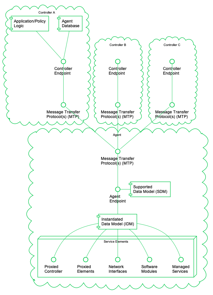
2.1.1 Agents
A USP Agent exposes (to Controllers) one or more Service Elements that are represented in its data model. It contains or references both an Instantiated Data Model (representing the current state of Service Elements it represents) and a Supported Data Model.
2.1.2 Controllers
A USP Controller manipulates (through Agents) a set of Service Elements that are represented in Agent data models. It may maintain a database of Agents, their capabilities, and their states, in any combination. A Controller usually acts as an interface to a user application or policy engine that uses the User Services Platform to address particular use cases.
2.2 Endpoint Identifier
Endpoints are identified by an Endpoint Identifier.
The Endpoint Identifier is a locally or globally unique USP layer identifier of an Endpoint. Whether it is globally or locally unique depends on the scheme used for assignment.
The Endpoint Identifier (ID) is used in the USP Record and various Parameters in a USP Message to uniquely identify Controller and Agent Endpoints. It can be globally or locally unique, either among all Endpoints or among all Controllers or all Agents, depending on the scheme used for assignment.
The Endpoint ID is comprised of two mandatory and one optionally
mandatory components: authority-scheme,
authority-id, and instance-id.
These three components are combined as:
authority-scheme ":" [authority-id] ":" instance-id
The format of the authority-id is dictated by the authority-scheme. The format of the instance-id is dictated either by the authority-scheme or by the entity identified by the authority-id.
When used in a certificate, an Endpoint ID is expressed as a urn in the bbf namespace as:
"urn:bbf:usp:id:" authority-scheme ":" [authority-id] ":" instance-id
When used anywhere else (e.g. in the to_id and
from_id of a USP Record), the namespace information is
omitted, and the Endpoint ID is expressed as:
authority-scheme ":" [authority-id] ":" instance-id
2.2.1 Use of authority-scheme and authority-id
The authority-scheme follows the following syntax:
authority-scheme = "oui" | "cid" | "pen" | "self" | "user" | "os" | "ops" | "uuid" | "imei" | "proto" | "doc" | "fqdn"
How these authority-scheme values impact the format and values of authority-id and instance-id is described below.
The authority defined by an OUI, CID, Private Enterprise Number (including OUI used in “ops” and “os” authority scheme), or fully qualified domain name is responsible for ensuring the uniqueness of the resulting Endpoint ID. Uniqueness can be global, local, unique across all Endpoints, or unique among all Controllers or all Agents. For the “user” authority scheme, the assigning user or machine is responsible for ensuring uniqueness. For the “self” authority scheme, the Endpoint is responsible for ensuring uniqueness.
R-ARC.0 - A Controller and Agent within the same USP Domain MAY use the same Endpoint ID.
R-ARC.1 - Endpoints MUST tolerate the same Endpoint ID being used by an Agent and a Controller in the same USP Domain.
R-ARC.2 - Endpoints that share the same Endpoint ID MUST NOT communicate with each other via USP.
No conflict identification or resolution process is defined in USP to deal with a situation where an Endpoint ID is not unique among either all Agents or all Controllers in whatever USP Domain it operates. Therefore, a non-unique Endpoint ID will result in unpredictable behavior. An Endpoint ID that changes after having been used to identify an Endpoint can also result in unpredictable behavior.
Unless the authority responsible for assigning an Endpoint ID assigns meaning to an Agent and Controller having the same Endpoint ID, no meaning can be construed. That is, unless the assigning authority specifically states that an Agent and Controller with the same Endpoint ID are somehow related, no relationship can be assumed to exist.
R-ARC.2a - Endpoints MUST follow the authority-scheme requirements outlined in the following table:
| authority-scheme | usage and rules for authority-id and instance-id |
|---|---|
oui |
authority-id MUST be an OUI
(now called “MAC Address Block”) assigned and registered by the IEEE
Registration Authority [7] to the entity
responsible for this Endpoint. authority-id MUST use hex encoding of the
24, 28, or 36-bit ID (resulting in 6, 7 or 9 hex characters).
instance-id syntax is defined by this entity, who is also
responsible for determining instance-id assignment mechanisms and for
ensuring uniqueness of the instance-id within the context of the OUI.
Example:oui:00256D:my-unique-bbf-id-42 |
cid |
authority-id MUST be a CID
assigned and registered by the IEEE Registration Authority [7] to the entity responsible for this
Endpoint. authority-id MUST use hex encoding of the 24-bit
ID (resulting in 6 hex characters).instance-id syntax is defined by this entity, who is also
responsible for determining instance-id assignment mechanisms and for
ensuring uniqueness of the instance-id within the context of the
CID.Example: cid:3AA3F8:my-unique-usp-id-42 |
pen |
authority-id MUST be a
Private Enterprise Number assigned and registered by IANA [6] to the entity responsible for this
Endpoint. authority-id MUST use decimal encoding of the
IANA-assigned number.instance-id syntax is defined by this entity, who is also
responsible for determining instance-id assignment mechanisms and for
ensuring uniqueness of the instance-id within the context of the Private
Enterprise Number.Example: pen:3561:my-unique-bbf-id-42 |
self |
When present, an authority-id
for “self” MUST be between 1 and 6 non-reserved characters
in length. When present, it is generated by the Endpoint. It is not
required to have an authority-id for
“self”.The Endpoint ID, including instance-id, is generated by the
Endpoint.The Endpoint MUST change its Endpoint ID if it ever encounters another Endpoint using the identical Endpoint ID. Example: self::my-Agent |
user |
An authority-id for
“user” MUST be between 0 and 6 non-reserved characters in
length.The Endpoint ID, including instance-id, is assigned to the
Endpoint via a user or management interface. |
os |
authority-id MUST be
zero-length.instance-idis
<OUI> "-" <SerialNumber>, with OUI
as defined above.Example: os::00256D-0123456789 |
ops |
authority-id MUST be
zero-length.instance-id is
<OUI> "-" <ProductClass> "-" <SerialNumber>,
with OUI as defined above.Example: ops::00256D-STB-0123456789 |
uuid |
authority-id MUST be
zero-length.instance-id is a UUID [16]Example: uuid::f81d4fae-7dec-11d0-a765-00a0c91e6bf6 |
imei |
authority-id MUST be
zero-length.instance-id is an IMEI [5] as defined by GSMA.Example: imei::990000862471854 |
proto |
authority-id MUST be between
0 and 6 non-reserved characters (except “.”) in length.“ proto” is used for prototyping purposes only. Any
authority-id and instance-id value (or scheme
for creating the value) is left to the prototyper.Example: proto::my-Agent |
doc |
authority-id MUST be between
0 and 6 non-reserved characters in length.“ doc” is used for documentation purposes only (for creating
examples in slide decks, tutorials, and other explanatory documents).
Any authority-id and instance-id value (or
scheme for creating the value) is left to the document creator. |
fqdn |
authority-id MUST be
zero-length.instance-id is a valid fully qualified domain name,
wildcards are not permitted.Example: fqdn::www.example.org |
R-ARC.3 - BBF OUI
(00256D) and Private Enterprise Number (3561)
are reserved for use in BBF documentation and BBF prototyping and MUST
NOT be used by any entity other than BBF.
R-ARC.4 - The
“proto” and “doc” authority-scheme values MUST
NOT be used in production environments.
The “proto” and “doc” values are intended
only for prototyping and documentation (tutorials, examples, etc.),
respectively.
R-ARC.4a - If the
authority-scheme fqdn is specified, the TLS
certificates presented by this endpoint MUST contain a
subjectAltName extension, allowing the use of the FQDN
specified by the instance-id value.
2.2.2 Use of instance-id
R-ARC.5 -
instance-id MUST be encoded using only the following
characters:
    instance-id = unreserved / pct-encoded
    unreserved = ALPHA / DIGIT / "-" / "." / "_"
    pct-encoded = "%" HEXDIG HEXDIG
The above expression uses the Augmented Backus-Naur Form (ABNF) notation of RFC 2234 [11], including the following core ABNF syntax rules defined by that specification: ALPHA (letters), DIGIT (decimal digits), HEXDIG (hexadecimal). It is taken from RFC 3986 [15] as the set of unreserved characters and percent-encoded characters that are acceptable for all components of a URI. This set is also allowed for use in URNs RFC 2141 [10], and all MTP headers.
R-ARC.6 - An
instance-id value MUST be no more than 50 characters in
length.
Shorter values are preferred, as end users could be exposed to Endpoint IDs. Long values tend to create a poor user experience when users are exposed to them.
2.3 Service Elements
“Service Element” is a general term referring to the set of Objects, Sub-Objects, Commands, Events, and Parameters that comprise a set of functionality that is manipulated by a Controller on an Agent. An Agent’s Service Elements are represented in a Data Model - the data model representing an Agent’s current state is referred to as its Instantiated Data Model, and the data model representing the Service Elements it supports is called its Supported Data Model. An Agent’s Data Model is referenced using Path Names.
2.4 Data Models
USP is designed to allow a Controller to manipulate Service Elements on an Agent using a standardized description of those Service Elements. This standardized description is known as an information model, and an information model that is further specified for use in a particular protocol is known as a “Data Model”.
Note: This should be understood by those familiar with CWMP. For those unfamiliar with that protocol, a Data Model is similar to a Management Information Base (MIB) used in the Simple Network Management Protocol (SNMP) or YANG definitions used in NETCONF.
This version of the specification defines support for the following Data Model(s):
- The Device:2 Data Model [3]
This Data Model is specified in XML. The schema and normative requirements for defining Objects, Parameters, Events, and Commands for the Device:2 Data Model [3] are defined in Broadband Forum TR-106 [2].
The use of USP with any of the above data models creates some dependencies on specific Objects and Parameters that must be included for base functionality.
2.4.1 Instantiated Data Model
An Agent’s Instantiated Data Model represents the Service Elements (and their state) that are currently represented by the Agent. The Instantiated Data Model includes a set of Objects, and the Sub-Objects (“children”), Parameters, Events, and Commands associated with those Objects.
2.4.2 Supported Data Model
An Agent’s Supported Data Model represents the Service Elements that an Agent understands. It includes references to the Data Model(s) that define the Objects, Parameters, Events, and Commands implemented by the Service Elements the Agent represents.
2.4.3 Objects
Objects are data structures that are defined by their Sub-Objects, Parameters, Events, Commands, and creation criteria. They are used to model resources represented by the Agent. Objects may be Single-Instance or Multi-Instance (also called a “Table”).
2.4.3.1 Single-Instance Objects
Single-Instance Objects are not tables and do not have more than one instance of them in the Agent. They are usually used to group Service Element functionality together to allow for easy definition and addressing.
2.4.3.2 Multi-Instance Objects
Multi-Instance” Objects are those Objects that can be the subject of “create” and “delete” operations (using the Add and Delete Messages, respectively), with each instance of the Object represented in the Instantiated Data Model with an Instance Identifier (see below). A Multi-Instance Object is also referred to as a “Table”, with each instance of the Object referred to as a “Row”. Multi-Instance Objects can be also the subject of a search.
2.4.4 Parameters
Parameters define the attributes or variables of an Object. They are retrieved by a Controller using the read operations of USP and configured using the update operations of USP (the Get and Set Messages, respectively). Parameters have data types and are used to store values.
2.4.5 Commands
Commands define Object specific methods within the Data Model. A Controller can invoke these methods using the Operate Message (see Defined Operations Mechanism. Commands have associated input and output arguments that are defined in the Data Model and used when the method is invoked and returned.
2.4.6 Events
Events define Object specific notifications within the Data Model. A Controller can subscribe to these events by creating instances of the Subscription table, which are then sent in a Notify request by the Agent (see Notifications and Subscription Mechanism). Events may also have information associated with them that are delivered in the Notify Request - this information is defined with the Event in the Data Model.
2.5 Path Names
A Path Name is a fully qualified reference to an Object, Object Instance, or Parameter in an Agent’s instantiated or Supported Data Model. The syntax for Path Names is defined in TR-106 [2].
R-ARC.7 - All USP Endpoints MUST support the Path Name syntax as defined in TR-106 [2].
Path Names are represented by a hierarchy of Objects (“parents”) and Sub-Objects (“children”), separated by the dot “.” character, ending with a Parameter if referencing a Parameter Path. There are six different types of Path Names used to address the data model of an Agent:
Object Path - This is a Path Name of either a Single-Instance Object, or the Path Name to a Multi-Instance Object (i.e., a Data Model Table). An Object Path ends in a “.” Character (as specified in TR-106 [2]), except when used in a reference Parameter (see Reference Following). When addressing a Table in the Agent’s Supported Data Model that contains one or more Multi-Instance Objects in the Path Name, the sequence “{i}” is used as a placeholder (see The GetSupportedDM Message). An Object Path, as with an Object Instance Path, is sometimes referred to as a “Partial Path”.
Object Instance Path - This is a Path Name to a Row in a Table in the Agent’s Instantiated Data Model (i.e., an Instance of a Multi-Instance Object). It uses an Instance Identifier to address a particular Instance of the Object. An Object Instance Path ends in a “.” Character (as specified in TR-106 [2]), except when used in a reference Parameter (see Reference Following). An Object Instance Path, as with an Object Path, is sometimes referred to as a “Partial Path”.
Parameter Path - This is a Path Name of a particular Parameter of an Object.
Command Path - This is a Path Name of an Object defined Operation.
Event Path - This is a Path Name of an Object defined Event.
Search Path - This is a Path Name that contains search criteria for addressing a set of Multi-Instance Objects and/or their Parameters. A Search Path may contain a Search Expression or Wildcard.
This creates two functions of Path Names: Addressing and Searching. The first five Path Names are used for addressing a particular Object, Parameter, Command, or Event. A Search Path uses Searching to return a set of Object Instances and/or their Parameters. When addressing, the expectation is that the Path Name will resolve to either 0 or 1 instance (and depending on the context, 0 instances could be an error). When searching, the expectation is that the Search Path will resolve to 0, 1, or many instances (and depending on the context, 0 instances is often not an error).
Note: When resolving a Path Name, the Agent is expected to use locally cached information and/or information that can be obtained rapidly and cheaply. Specifically, there is no expectation that the Agent would issue a network request in order to resolve a Path Name.
Note: Obviously only one form of addressing or searching can be used for a given Instance Identifier in a Path Name, but different forms of addressing can be used if more than one Instance Identifier needs to be specified in a Path Name.
For example, the following Path Name uses Unique Key Addressing for the Interface table but a Search Expression for the IPv4Address table to select Enabled IPv4 Addresses associated with the “eth0” IP Interface:
Device.IP.Interface.[Name=="eth0"].IPv4Address.[Status=="Enabled"].IPAddress
2.5.1 Relative Paths
Several USP Messages make use of Relative Paths to address Objects or Parameters. A Relative Path is used to address the child Objects and Parameters of a given Object Path or Object Instance Path. To build a Path Name using a Relative Path, a USP Endpoint uses a specified Object Path or Object Instance Path, and concatenates the Relative Path. This allows some efficiency in Requests and Responses when passing large numbers of repetitive Path Names. This Relative Path may include instance identifiers to Multi-Instance Objects.
For example, for an Object Path of:
Device.WiFi.Radio.1.Relative Paths would include Parameters:
Status
SupportedStandards
OperatingStandards
Etc., as well as the following Sub-Object and its Parameters:
Stats.BytesSent
Stats.BytesReceived
Etc.
2.5.2 Using Instance Identifiers in Path Names
2.5.2.1 Addressing by Instance Number
Instance Number Addressing allows an Object Instance to be addressed by using its Instance Number in the Path Name. An Instance Number is expressed in the Path Name as a positive integer (>=1) with no additional surrounding characters. The Instance Number assigned by the Agent is arbitrary.
R-ARC.8 - The assigned Instance Number MUST persist unchanged until the Object Instance is subsequently deleted (either by the USP Delete Message or through some external mechanism). This implies that the Instance Number MUST persist across a reboot of the Agent, and that the Agent MUST NOT allow the Instance Number of an existing Object Instance to be modified by an external source.
For example, the Device.IP.Interface table entry with an
Instance Number of 3 would be addressed with the following Path Name:
Device.IP.Interface.3.
2.5.2.2 Addressing by Unique Key
Key-based addressing allows an Object Instance to be addressed by using a Unique Key (as defined in the Device:2 Data Model [3]) in the Path Name.
Note: Controller and Agent interoperability is greatly affected by an Agent’s implementation of Unique Keys. While this specification does not aim to overlap its requirements to those of TR-181 [3], it is imperative that an Agent implements Unique Keys for every Multi-Instance object in its Supported Data Model.
Unique Keys used for addressing are expressed in the Path Name by using square brackets surrounding a string that contains the name and value of the Unique Key Parameter using the equality operator (==).
For example, the Device.IP.Interface table has two
separate unique keys: Name and Alias. It could
be addressed with the following Path Names:
Device.IP.Interface.[Name=="eth0"]
Device.IP.Interface.[Alias=="WAN"]
If an Object has a multi-parameter unique key, then the Instance Identifier specifies all of the key’s Parameters using the AND (&&) logical operator (the Parameter order is not significant).
For example, the Device.NAT.PortMapping table has a
multi-parameter unique key consisting of RemoteHost, ExternalPort, and
Protocol. It could be addressed with the following Path Name:
Device.NAT.PortMapping.[RemoteHost==""&&ExternalPort==0&&Protocol=="TCP"].
Note: Addressing by Unique Key uses the same syntax as Searching with Expressions. If a multi-parameter unique key expression omits any of the key’s Parameters then it’s a search (which might match multiple instances) rather than an address (which can’t match multiple instances).
2.5.3 Searching
Searching is a means of matching 0, 1 or many instances of a Multi-Instance Object by using the properties of Object. Searching can be done with Expressions or Wildcards.
2.5.4 Searching with Expressions
Search Paths that use expressions are enclosed in square brackets as the Instance Identifier within a Path Name.
R-ARC.9 - An Agent MUST return Path Names that include all Object Instances that match the criteria of a given Search Path.
The basic format of a Search Path is:
Device.IP.Interface.[<expression>].Status
An Expression consists of one or more Expression Components that are concatenated by either the AND (&&) logical operator or the OR (||) logical operator. An expression may not contain a mix of operators.
The basic format of a Search Path with the Expression element expanded is:
Device.IP.Interface.[<expression component>&&<expression component>].Status
An Expression Component is a combination of an Expression Parameter followed by an Expression Operator followed by an Expression Constant.
The basic format of a Search Path with the Expression Component element expanded is:
Device.IP.Interface.[<expression parameter><expression operator><expression constant>].Status
Further, this Relative Path can’t include any child tables. (Note: this is never necessary because any child tables that need to be referenced in the Search Path can and should have their own Expression)
An Expression Operator dictates how the Expression Component will be evaluated. The supported operators are equals (==), not equals (!=), contains (~=), less than (<), greater than (>), less than or equal (<=) and greater than or equal (>=).
An Expression Parameter will always be of the type defined in the data model. Expression operators will only evaluate for appropriate data types. The literal value representations for all data types are found in TR-106 [2]. For string and boolean types, and also the Unknown Time dateTime value (cf. TR-106 Section 3.2.1 [2]), only the ‘==’ and ‘!=’ operators are valid.
The ‘~=’ operator is only valid for comma-separated lists. It is used to check whether a list contains a certain element using an exact match of the element. The Expression Constant used in the Search Expression must be of the same type as the values in the list. For example, for a list of integers, the Expression Constant must also be an integer.
Note: Literal values are conceptually converted to a suitable
internal representation before comparison. For example, int
values 123, +123 and 0123 all
represent the same value, and so do boolean values
1 and true.
The Expression Constant is the value that the Expression Parameter is being evaluated against; Expression Parameters must match the type as defined for the associated Parameter in the Device:2 Data Model [3].
Note: String values are enclosed in double quotes. In order to allow a string value to contain double quotes, quote characters can be percent-escaped as %22 (double quote). Therefore, a literal percent character has to be quoted as %25.
The use of whitespace on either side of an Expression Operator is
allowed, but its support is not required. Controllers cannot assume that
an Agent tolerates whitespace. An example of an Expression with
whitespace would be [Type == "Normal"] (which would be
[Type=="Normal"] without whitespace).
R-ARC.9a - Agents SHOULD tolerate whitespace on either side of an Expression Operator.
R-ARC.9b - Controllers SHOULD NOT include whitespace on either side of an Expression Operator.
2.5.4.0.1 Search Expression Examples
Valid Searches:
Status for all IP Interfaces with a “Normal” type:
Device.IP.Interface.[Type=="Normal"].StatusIPv4 Addresses for all IP Interfaces with a Normal type and a Static addressing type:
Device.IP.Interface.[Type=="Normal"].IPv4Address.[AddressingType=="Static"].IPAddressIPv4 Addresses for all IP Interfaces with a Normal type and Static addressing type that have at least 1 Error Sent:
Device.IP.Interface.[Type=="Normal"&&Stats.ErrorsSent>0].IPv4Address.[AddressingType=="Static"].IPAddressCurrent profiles used by all DSL lines which are enabled:
Device.DSL.Line.[Enable==true].CurrentProfileor
Device.DSL.Line.[Enable==1].CurrentProfileAll IPv6 Addresses of all interfaces with a lifetime expiring before 2021-06-06 08:00 UTC:
Device.IP.Interface.*.IPv6Address.[ValidLifetime<2021-06-06T08:00:00Z].IPAddressAll Parameters of all connected USB devices of class 0x08 (Mass Storage Device):
Device.USB.USBHosts.Host.*.Device.[DeviceClass==08].All Parameters of all PCP servers with IPv6Firewall capabilities:
Device.PCP.Client.*.Server.[Capabilities~="IPv6Firewall"].All Parameters of all PeriodicStatistics SampleSets that collected data for 5 seconds:
Device.PeriodicStatistics.SampleSet.[SampleSeconds~=5].
Searches that are NOT VALID:
Invalid because the Expression is empty:
Device.IP.Interface.[].Invalid because the Expression Component has an Expression Parameter that descends into a child table (always need to use a separate Expression Variable for each child table instance):
Device.IP.Interface.[Type=="Normal"&&IPv4Address.*.AddressingType=="Static"].StatusInvalid because the search expression uses curly brackets:
Device.IP.Interface.{Type=="Normal"}.StatusInvalid because the
EnableParameter is of typebooleanand not astringor derived fromstring:Device.DSL.Line.[Enable=="true"].CurrentProfile
2.5.5 Searching by Wildcard
Wildcard-based searching is a means of matching all currently existing Instances (whether that be 0, 1 or many instances) of a Multi-Instance Object by using a wildcard character “*” in place of the Instance Identifier.
R-ARC.10 - An Agent MUST return Path Names that include all Object Instances that are matched by the use of a Wildcard.
Examples:
All Parameters for all IP Interfaces that currently exist
Device.IP.Interface.*.
Type of each IP Interface that currently exists
Device.IP.Interface.*.Type
2.6 Other Path Decorators
2.6.1 Reference Following
The Device:2 Data Model [3] contains Parameters that reference other Parameters or Objects. The Reference Following mechanism allows references to Objects (not Parameters) to be followed from inside a single Path Name. Reference Following is indicated by a “+” character after the Parameter Path, referencing the Object followed by a “.”, optionally followed by a Relative Object or Parameter Path that are children of the Referenced Object.
For example, Device.NAT.PortMapping.{i}.Interface
references an IP Interface Object
(Device.IP.Interface.{i}.) and that Object has a Parameter
called “Name”. With Reference Following, a Path Name of
Device.NAT.PortMapping.1.Interface+.Name references the
“Name” Parameter of the Interface Object that
the PortMapping is associated with (i.e. it is the
equivalent of using Device.IP.Interface.1.Name as the Path
Name).
The steps that are executed by the Agent when following the reference in this example would be:
Retrieve the appropriate instance of the
PortMappingObject based on the Instance Number Addressing informationRetrieve the value of the reference Parameter that contains the reference, Interface, which in this case has the value “
Device.IP.Interface.1”Replace the preceding Path Name (
Device.NAT.PortMapping.1.Interface+) with the value retrieved in Step 2Append the remainder of the Path Name (
.Name), which builds the Path Name:Device.IP.Interface.1.NameUse
Device.IP.Interface.1.Nameas the Path Name for the action
Note: It should be noted that according to the Device:2 Schema [2], reference Parameters:
- Always contain Path Names (not Search Expressions)
- When configured, can be configured using Path Names using Instance Number Addressing or Unique-Key Addressing, however:
- When the value of a reference Parameter is read, all Instance Identifiers are returned as Instance Numbers.
R-ARC.11 - A USP Agent MUST support the ability to use Key-based addressing in reference values.
For example, the following Path Names might illustrate a reference to
the same Object (defined as having the Parameter named
KeyParam as unique key) instance using an Instance Number
and then a key value:
- Object.SomeReferenceParameter = “Object.FooObject.5”
- Object.SomeReferenceParameter = ‘Object.FooObject.[KeyParam==“KeyValueForInstance5”]’
In the first example, the reference points to the FooObject with
Instance Number 5. In the second example, the reference points to the
FooObject with a KeyParam value of
“KeyValueForInstance5”.
R-ARC.12 - The following requirements relate to reference types and the associated Agent behavior:
- An Agent MUST reject an attempt to set a strong reference Parameter if the new value does not reference an existing Parameter or Object.
- An Agent MUST NOT reject an attempt to set a weak reference Parameter because the new value does not reference an existing Parameter or Object.
- An Agent MUST change the value of a non-list-valued strong reference Parameter to a null reference when a referenced Parameter or Object is deleted.
- An Agent MUST remove the corresponding list item from a list-valued strong reference Parameter when a referenced Parameter or Object is deleted.
- An Agent MUST NOT change the value of a weak reference Parameter when a referenced Parameter or Object is deleted.
2.6.1.1 List of References
The USP data models have Parameters whose values contain a list of
references to other Parameters or Objects. This section explains how the
Reference Following mechanism allows those references to be followed
from inside a single Path Name. The Reference Following syntax as
defined above still applies, but the “+” character is
preceded by a means of referencing a list item or items.
The additional syntax consists of a “
#” character followed by a list item number (1-indexed), which is placed between the Parameter name and the “+” character.- The “
#” and list item number are optional. If they are omitted, the first list item is used, i.e., “ReferenceParameter+” means the same as “ReferenceParameter#1+”.
- The “
To follow all references in the list, use a wildcard (“
*”) character instead of a list item number, i.e., “ReferenceParameter#*+”.
For example, Device.WiFi.SSID.{i}.LowerLayers references
a list of Wi-Fi Radio Object (defined as
Device.WiFi.Radio.{i}.) Instances that are associated with
the SSID. This Object has a Name Parameter; so when
following the first reference in the list of references a Path Name of
Device.WiFi.SSID.1.LowerLayers#1+.Name references the Name
of the Wi-Fi Radio associated with this SSID Object Instance.
The steps that are executed by the Agent when following the reference in this example would be:
Retrieve the appropriate
Device.WiFi.SSID.{i}instance based on the Instance Number Addressing informationRetrieve the value of the LowerLayers Parameter, which in this case has a value of “
Device.WiFi.Radio.1, Device.WiFi.Radio.2”Retrieve the first list item within the value retrieved in Step 2 (i.e., “
Device.WiFi.Radio.1”)Replace the preceding Path Name (
Device.WiFi.SSID.1.LowerLayers#1+) with the value retrieved in Step 3Append the remainder of the Path Name (
.Name), resulting in a Path Name of:Device.WiFi.Radio.1.NameUse
Device.WiFi.Radio.1.Nameas the Path Name for the action
2.6.1.2 Search Expressions and Reference Following
The Reference Following and Search Expression mechanisms can be combined.
For example, reference the Signal Strength of all Wi-Fi Associated Devices using the “ac” Operating Standard on the “MyHome” SSID, you would use the Path Name:
Device.WiFi.AccessPoint.[SSIDReference+.SSID=="MyHome"].AssociatedDevice.[OperatingStandard=="ac"].SignalStrength
2.6.2 Operations and Command Path Names
The Operate Message allows a USP Controller to execute Commands defined in the USP data models. Commands are synchronous or asynchronous operations that don’t fall into the typical REST-based concepts of CRUD-N that have been incorporated into the protocol as specific Messages. Commands are addressed like Parameter Paths that end with parentheses “()” to symbolize that it is a Command.
For example:
Device.IP.Interface.[Name=="eth0"].Reset()
2.6.3 Event Path Names
The Notify request allows a type of generic event (called Event) message that allows a USP Agent to emit events defined in the USP data models. Events are defined in and related to Objects in the USP data models like commands. Events are addressed like Parameter Paths that end with an exclamation point “!” to symbolize that it is an Event.
For example: Device.Boot!
2.7 Data Model Path Grammar
Expressed as a Backus-Naur Form (BNF) for context-free grammars, the Path Name lexical rules for referencing the Instantiated Data Model are:
idmpath   ::= objpath | parampath | cmdpath | evntpath
objpath   ::= name '.' (name (('.' inst)|(reffollow '.' name) )? '.')*
parampath ::= objpath name
cmdpath   ::= objpath  name '()'
evntpath  ::= objpath  name '!'
inst      ::= posnum | expr | '*'
expr      ::= '[' ( andexpr | orexpr ) ']'
andexpr   ::=  exprcomp ( '&&' exprcomp )*
orexpr    ::=  exprcomp ( '||' exprcomp )*
exprcomp  ::= relpath oper value
relpath   ::= name (reffollow? '.' name )*
reffollow ::=  ( '#' (posnum | '*') '+' )|  '+'
oper      ::= '==' | '!=' | '~=' | '<' | '>' | '<=' | '>='
value     ::= literal | number
name      ::= [A-Za-z_] [A-Za-z_0-9]*
literal   ::= '"' [^"]* '"'
posnum    ::= [1-9] [0-9]*
number    ::= '0' | ( '-'? posnum )
The Path Name lexical rules for referencing the Supported Data Model are:
sdmpath   ::= name '.' ( name '.' ( ( posnum | '{i}' ) '.' )? )* name?
name      ::= [A-Za-z_] [A-Za-z_0-9]*
posnum    ::= [1-9] [0-9]*
2.7.1 BNF Diagrams for Instantiated Data Model
idmpath:
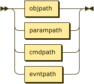
idmpath ::= objpath | parampath | cmdpath | evntpath
objpath:
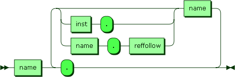
objpath ::= name ‘.’ ( name ( ‘.’ inst | reffollow ‘.’ name)? ‘.’ )*
referenced by:
parampath:

parampath ::= objpath name
referenced by:
cmdpath:

cmdpath ::= objpath name ‘()’
referenced by:
evntpath:

evntpath ::= objpath name ‘!’
referenced by:
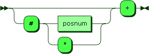
inst:
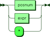
inst ::= posnum | expr | ’*’
referenced by:
expr:
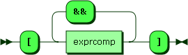
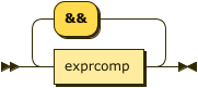
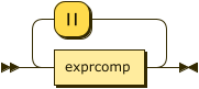
expr ::= ‘[’ ( andexpr | orexpr ) ’]’
andexpr ::= exprcomp ( ‘&&’ exprcomp )
orexpr ::= exprcomp ( ‘||’ exprcomp )
referenced by:
exprcomp:

exprcomp ::= relpath oper value
referenced by:
relpath:
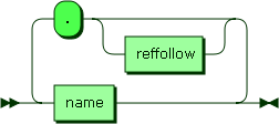
relpath ::= name ( reffollow? ‘.’ name )*
referenced by:
reffollow:
reffollow ::= ( ‘#’ ( posnum | ’*’ ) )? ‘+’
referenced by:
oper:
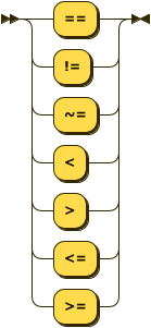
oper ::= ‘==’ | ‘!=’ | ‘~=’ | ‘<’ | ‘>’ | ‘<=’ | ‘>=’
referenced by:
value:
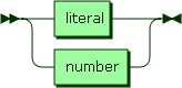
value ::= literal | number
referenced by:
name:
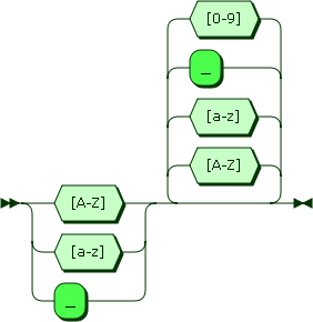
name ::= [A-Za-z_] [A-Za-z_0-9]*
referenced by:
literal:

literal ::= ‘“’ [^"]* ‘“’
referenced by:
number:
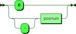
number ::= ‘0’ | ‘-’? posnum
referenced by:
posnum:
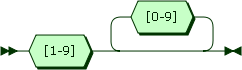
posnum ::= [1-9] [0-9]*
referenced by:
2.7.2 BNF Diagrams for Supported Data Model
sdmpath:
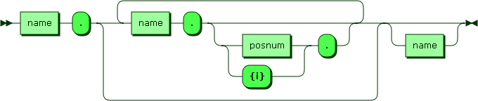
sdmpath ::= name ‘.’ ( name ‘.’ ( ( posnum | ‘{i}’ ) ‘.’ )? )* name?
name:
name ::= [A-Za-z_] [A-Za-z_0-9]*
referenced by:
posnum:
posnum ::= [1-9] [0-9]*
referenced by:
3 Discovery and Advertisement
Discovery is the process by which USP Endpoints learn the USP properties and MTP connection details of another Endpoint, either for sending USP Messages in the context of an existing relationship (where the Controller’s USP Endpoint Identifier, credentials, and authorized Role are all known to the Agent) or for the establishment of a new relationship.
Advertisement is the process by which USP Endpoints make their presence known (or USP Endpoint presence is made known) to other USP Endpoints.
3.1 Controller Information
An Agent that has a USP relationship with a Controller needs to know that Controller’s Endpoint Identifier, credentials, and authorized Role.
An Agent that has a USP relationship with a Controller needs to obtain information that allows it to determine at least one MTP, IP address, port, and resource path (if required by the MTP) of the Controller. This may be a URL with all of these components, a FQDN that resolves to provide all of these components via DNS-SD records, or mDNS discovery in the LAN.
Example mechanisms for configuration include but are not limited to:
- Pre-configured in firmware
- Configured by an already-known-and-trusted Controller
- Configured through a separate bootstrap mechanism such as a user interface or other management interface.
- DHCP, DNS, or mDNS.
R-DIS.0 - An Agent that supports
USP configuration of Controllers MUST implement the
Device.LocalAgent.Controller Object as defined in the
Device:2 Data Model [3].
The Agent can be pre-configured with trusted root certificates or trusted certificates to allow authentication of Controllers. Other trust models are also possible, where an Agent without a current Controller association will trust the first discovered Controller, or where the Agent has a UI that allows a User to indicate whether a discovered Controller is authorized to configure that Agent.
3.2 Required Agent Information
A Controller that has a relationship with an Agent needs to know the Agent’s Endpoint Identifier, connectivity information for the Agent’s MTP(s), and credentials.
Controllers acquire this information upon initial connection by an Agent, though a LAN based Controller may acquire an Agent’s MTP information through mDNS Discovery. It is each Controller’s responsibility to maintain a record of known Agents.
3.3 Use of DHCP for Acquiring Controller Information
DHCP can be employed as a method for Agents to discover Controllers. The DHCPv4 Vendor-Identifying Vendor-Specific Information Option [14] (option code 125) and DHCPv6 Vendor-specific Information Option [13] (option code 17) can be used to provide information to Agents about a single Controller. The options that may be returned by DNS are shown below. Description of these options can be found in the Device:2 Data Model [3].
R-DIS.1 - If an Agent is
configured to request Controller DHCP information, the Agent MUST
include in its DHCPv4 requests a DHCPv4 V-I Vendor Class Option (option
124) and in its DHCPv6 requests a DHCPv6 Vendor Class (option 16). This
option MUST include the Broadband Forum Enterprise Number
(3561 decimal, 0x0DE9 hex) as an
enterprise-number, and the string “usp” (all lower case) in
a vendor-class-data instance associated with this enterprise-number.
R-DIS.1a - The Agent MUST decode all received options as strings (provisioning code, wait interval, and interval multiplier are not decoded as numeric fields).
R-DIS.1b - The Agent MUST interpret a received URL or FQDN of the Controller as either an absolute URL or FQDN.
R-DIS.1c - If the Agent receives an encapsulated option value that is null terminated, the Agent MUST accept the value provided, and MUST NOT interpret the null character as part of the value.
The Role to associate with a DHCP-discovered Controller is programmatically determined (see Authentication and Authorization).
Note: Requirement R-DIS.2 was removed in USP 1.2.
See Using DNS for requirements on resolving URLs and FQDNs provided by DHCP.
ISPs are advised to limit the use of DHCP for configuration of a Controller to situations in which the security of the link between the DHCP server and the Agent can be assured by the service provider. Since DHCP does not itself incorporate a security mechanism, it is a good idea to use pre-configured certificates or other means of establishing trust between the Agent and a Controller discovered by DHCP.
3.3.1 DHCP Options for Controller Discovery
| Encapsulated Option | DHCPv4 Option 125 | DHCPv6 Option 17 | Parameter in the Device:2 Data Model [3] |
|---|---|---|---|
| URL or FQDN of the Controller | 25 |
25 |
Dependent on MTP |
| Provisioning code | 26 |
26 |
Device.LocalAgent.Controller.{i}.ProvisioningCode |
| USP retry minimum wait interval | 27 |
27 |
Device.LocalAgent.Controller.{i}.USPNotifRetryMinimumWaitInterval |
| USP retry interval multiplier | 28 |
28 |
Device.LocalAgent.Controller.{i}.USPNotifRetryIntervalMultiplier |
| Endpoint ID of the Controller | 29 |
29 |
Device.LocalAgent.Controller.{i}.EndpointID |
3.4 Use of DHCP for Exchanging GatewayInfo
This section contains a set of USP requirements related to a mechanism that was originally defined in the CPE WAN Management Protocol [1] (CWMP), which provides a way for a CWMP Gateway and an End Device to exchange information via DHCP options to populate data model objects with their reciprocal information. The purpose of populating this information is to provide an ACS or USP Controller with the ability to determine whether the Gateway and Device are on the same LAN. The USP requirements defined in this section identify what USP-enabled devices (Gateways and End Devices) need to do to interoperate with CWMP-enabled devices without changing any CWMP functionality, so it is mostly a replication of those CWMP requirements from a USP-enabled device perspective.
3.4.1 Exchanging DHCP Options
This section outlines the DHCP information USP Agents exchange to provide details about the devices on the LAN, as well as the Service Elements that are updated. This allows a USP Agent to recognize a CWMP Client that supports the Device-Gateway Association within the LAN, and a CWMP Client to recognize a USP Agent.
R-DIS.2a - When an Agent sends a DHCPv4 requests (DHCPDISCOVER, DHCPREQUEST, and DHCPINFORM) or DHCPv6 requests (SOLICIT, REQUEST, RENEW, and INFORMATION-REQUEST) it MUST include the Encapsulation Options for requests below.
3.4.2 DHCP Encapsulated Vendor-Specific Option-Data fields for DHCP requests
| Encapsulated Option | DHCPv4 Option 125 | DHCPv6 Option 17 | Parameter in the Device:2 Data Model [3] |
|---|---|---|---|
| DeviceManufacturerOUI | 1 |
11 |
Device.DeviceInfo.ManufacturerOUI |
| DeviceSerialNumber | 2 |
12 |
Device.DeviceInfo.SerialNumber |
| DeviceProductClass | 3 |
13 |
Device.DeviceInfo.ProductClass |
These Encapsulated Options are carried in DHCPv4 V-I Vendor Class Option (option 125) or DHCPv6 V-I Vendor Class Option (option 17) with an element identified with the IANA Enterprise Number for the Broadband Forum that follows the format defined below. The IANA Enterprise Number for the Broadband Forum is 3561 in decimal (the ADSL Forum entry in the IANA Private Enterprise Numbers registry).
R-DIS.2b - If an Agent receives the encapsulation options for requests above, then it MUST respond with the Encapsulated Options for a response in the DHCPv4 responses (DHCPOFFER and DHCPACK) and DHCPv6 responses (ADVERTISE and REPLY) below. The responses are only included if the request options are received.
3.4.3 DHCP Encapsulated Vendor-Specific Option-Data fields for Agent
| Encapsulated Option | DHCPv4 Option 125 | DHCPv6 Option 17 | Parameter in the Device:2 Data Model [3] |
|---|---|---|---|
| DeviceManufacturerOUI | 4 |
14 |
Device.DeviceInfo.ManufacturerOUI |
| DeviceSerialNumber | 5 |
15 |
Device.DeviceInfo.SerialNumber |
| DeviceProductClass | 6 |
16 |
Device.DeviceInfo.ProductClass |
These Encapsulated Options are carried in DHCPv4 V-I Vendor Class Option (option 125) or DHCPv6 V-I Vendor Class Option (option 17) with an element identified with the IANA Enterprise Number for the Broadband Forum that follows the format defined below. The IANA Enterprise Number for the Broadband Forum is 3561 in decimal (the ADSL Forum entry in the IANA Private Enterprise Numbers registry).
R-DIS.2c - When an Agent receives
a DHCPv4 response (DHCPOFFER or DHCPACK) or a DHCPv6 response (ADVERTISE
or REPLY) with this information, it MUST populate the
Device.GatewayInfo Object as defined in the Device:2 Data
Model [3]. Specifically, it MUST set the
parameters ManufacturerOUI, ProductClass and
SerialNumber, if present and
ManagementProtocol MUST be set to “CWMP”. If any of the
parameters are not present then they MUST be set to an empty string. If
the DHCP release expires, or the USP Endpoint doesn’t receive this
information, the Parameters in the Device.GatewayInfo
Object MUST be set to an empty strings.
R-DIS.2d - When an Agent performs
mDNS discovery (see Discovery
and Advertisement) and receives a PTR record (see DNS-SD Records) that
match the same IP address as the DHCP response from (R-DIS.2c), it MUST also set the
Device.GatewayInfo.ManagementProtocol Parameter to “USP”,
and Device.GatewayInfo.EndpointID Parameter to the USP
EndpointID received in the PTR record.
3.5 Using mDNS
R-DIS.3 - If mDNS discovery is supported by a USP Endpoint, the USP Endpoint MUST implement mDNS client and server functionality as defined in RFC 6762 [24].
R-DIS.4 - If mDNS advertisement for an MTP is enabled on an Endpoint, the Endpoint MUST listen for messages using that MTP from other Endpoints requesting establishment of USP communication over that MTP.
R-DIS.5 - If mDNS is enabled, a
USP Endpoint MUST use mDNS to resolve a FQDN with domain
“.local.”.
In general, the expectation is that Agents will advertise themselves,
so they will be discoverable by Controllers. Controllers are not
expected to advertise themselves, but are expected to discover Agents
and respond to applicable mDNS requests from Agents. Agents will use
mDNS to resolve a Controller “.local.” FQDN (and get DNS-SD
records) when the Agent needs to send a Notification to that
Controller.
3.6 Using DNS
Requirements for implementation of a DNS client and configuration of the DNS client with DNS server address(es) (through static configuration, DHCPv4, DHCPv6, or Router Solicitation) are not provided. These are sufficiently well-known that they were not considered necessary for this specification. If the Agent knows of no DNS Server, it cannot do DNS resolution.
R-DIS.6 - If DNS is enabled, an Endpoint MUST use DNS to request IP address(es) (A and/or AAAA records, depending on configured IP stacks) for a FQDN with domain other than ones used for mDNS (R-DIS.5).
If the Endpoint is programmatically set to request other resource records, it will request those, too.
R-DIS.7 - If the Agent is resolving an FQDN for a Controller, and the MTP or resource path are unknown, the Agent MUST request DNS-SD information (PTR, SRV and TXT resource records) in addition to A, AAAA or other resource records it is programmatically set to request.
3.7 DNS-SD Records
DNS Service Discovery (DNS-SD) RFC 6763 [25] is a mechanism for naming and structuring DNS resource records to facilitate service discovery. It can be used to create DNS records for USP Endpoints, so they can be discoverable via DNS PTR queries RFC 1035 [8] or Multicast DNS (mDNS) RFC 6762 [24]. DNS-SD uses DNS SRV and TXT records to express information about “services”, and DNS PTR records to help locate the SRV and TXT records. To discover these DNS records, DNS or mDNS queries can be used. RFC 6762 [24] recommends using the query type PTR to get both the SRV and TXT records. A and AAAA records will also be returned, for address resolution.
The format of a DNS-SD Service Instance Name (which is the resource
record (RR) Name of the DNS SRV and TXT records) is
“<Instance>.<Service>.<Domain>”.
<Instance> will be the USP Endpoint Identifier of the
USP Endpoint.
R-DIS.8 - USP Endpoint DNS-SD records MUST include the USP Endpoint Identifier of the USP Endpoint as the DNS-SD Service Instance Name.
Service Name values registered by BBF with
IANA used by USP are shown below. As described in RFC 6763 [25], the <Service>
part of a Service Instance Name is constructed from these values as
“_<Service Name>._<Transport Protocol>” (e.g.,
“_usp-agt-ws._tcp”).
3.7.1 IANA-Registered USP Service Names
| Service Name | Transport Protocol | MTP | Type of USP Endpoint |
|---|---|---|---|
usp-agt-coap |
udp | CoAP | Agent |
usp-agt-mqtt |
tcp | MQTT | Agent |
usp-agt-stomp |
tcp | STOMP | Agent |
usp-agt-ws |
tcp | WebSocket | Agent |
usp-ctr-coap |
udp | CoAP | Controller |
usp-ctr-mqtt |
tcp | MQTT | Controller |
usp-ctr-stomp |
tcp | STOMP | Controller |
usp-ctr-ws |
tcp | WebSocket | Controller |
DNS PTR records with a service subtype identifier (e.g.,
._<subtype>._usp-agt-ws._tcp.<Domain>) in the
RR can be used to provide searchable simple (single layer) functional
groupings of USP Agents. The registry of subtypes for Service Names
registered by BBF is listed at www.broadband-forum.org/assignments.
DNS SRV and TXT records can be pointed to by multiple PTR records, which
allow a USP Endpoint to potentially be discoverable as belonging to
various functional groupings.
DNS TXT records allow for a small set of additional information to be included in the reply sent to the querier. This information cannot be used as search criteria. The registry of TXT record attributes for BBF Service Names are listed at www.broadband-forum.org/assignments.
R-DIS.9 - Agent DNS-SD records MUST include a TXT record with the “path” and “name” attributes.
R-DIS.10 - The “name” attribute
included in the Agent DNS-SD records MUST be identical to the
FriendlyName Parameter defined in the Device:2 Data Model
[3], if the FriendlyName
Parameter is implemented.
R-DIS.11 - Controller DNS-SD records MUST include a TXT record with the “path” attribute.
The “path” attribute is dependent on each MTP.
R-DIS.11a - If a USP Endpoint requires MTP encryption to be used when connecting to its advertised service, it MUST include the “encrypt” parameter in the TXT record.
The “encrypt” parameter is Boolean and does not require a value to be specified. Its presence means MTP encryption is required when connecting to the advertised service. Its absence means MTP encryption is not required when connecting to the advertised service.
The TXT record can include other attributes defined in the TXT record attribute registry, as well.
Whether a particular USP Endpoint responds to DNS or mDNS queries or populates (through configuration or mDNS advertisement) their information in a local DNS-SD server can be a configured option that can be enabled/disabled, depending on the intended deployment usage scenario.
3.7.2 Example Controller Unicast DNS-SD Resource Records
    ; One PTR record for each supported MTP
    _usp-ctr-ws._tcp.host.example.com      PTR <USP ID>._usp-ctr-ws._tcp.example.com.

    ; One SRV+TXT (DNS-SD Service Instance) record for each supported MTP
    <USP ID>._usp-ctr-ws._tcp.example.com.   SRV 0 1 5684 host.example.com.
    <USP ID>._usp-ctr-ws._tcp.example.com.   TXT "<length byte>path=<pathname><length byte>encrypt"

    ; Controller A and AAAA records
    host.example.com.  A      192.0.2.200
    host.example.com.  AAAA   2001:db8::200
3.7.3 Example Agent Multicast DNS-SD Resource Records
    ; One PTR record (DNS-SD Service) for each supported MTP
    _usp-agt-ws._tcp                 PTR <USP ID>._usp-agt-ws._tcp.local.

    ; One PTR record (DNS-SD Service Subtype) for each supported MTP per device type
    _iot-device._sub._usp-agt-ws._tcp    PTR <USP ID>._usp-agt-ws._tcp.local.
    _gateway._sub._usp-agt-ws._tcp       PTR <USP ID>._usp-agt-ws._tcp.local.

    ; One SRV+TXT record (DNS-SD Service Instance) for each supported MTP
    <USP ID>._usp-agt-ws._tcp.local.    SRV 0 1 5684 <USP ID>.local.
    <USP ID>._usp-agt-ws._tcp.local.    TXT "<length byte>path=<pathname><length byte>name=kitchen light<length byte>encrypt"

    ; Agent A and AAAA records
    <USP ID>.local.  A      192.0.2.100
    <USP ID>.local.  AAAA   2001:db8::100
3.7.4 Example Controller Multicast DNS-SD Resource Records
LAN Controllers do not need to have PTR records, as they will only be queried using the DNS-SD instance identifier of the Controller.
    ; One SRV+TXT record (DNS-SD Service Instance) for each supported MTP
    <USP ID>._usp-ctr-ws._tcp.local.    SRV 0 1 5683 <USP ID>.local.
    <USP ID>._usp-ctr-ws._tcp.local.    TXT "<length byte>path=<pathname>"

    ; Controller A and AAAA records
    <USP ID>.local.  A      192.0.2.200
    <USP ID>.local.  AAAA   2001:db8::200
3.8 Using the SendOnBoardRequest() operation and OnBoardRequest notification
An “OnBoardRequest” notification can be sent by an Agent to a Controller to begin an on-boarding process (for example, when the Agent first comes online and discovers a Controller using DHCP). Its use is largely driven by policy, but there is a mechanism other Controllers can use to ask an Agent to send “OnBoardRequest” to another Controller: the SendOnBoardRequest() command is defined in the Device:2 Data Model [3]. See Notification Types for additional information about the OnBoardRequest notification.
4 Message Transfer Protocols
USP messages are sent between Endpoints over one or more Message Transfer Protocols.
Note: Message Transfer Protocol was a term adopted to avoid confusion with the term “Transport”, which is often overloaded to include both application layer (e.g. WebSocket) and the actual OSI Transport layer (e.g. TCP). Throughout this document, Message Transfer Protocol (MTP) refers to application layer transport.
4.1 Generic Requirements
The requirements in this section are common to all MTPs.
4.1.1 Supporting Multiple MTPs
Agents and Controllers may support more than one MTP. When an Agent supports multiple MTPs, the Agent may be configured with Parameters for reaching a particular Controller across more than one MTP. When an Agent needs to send a Notification to such a Controller, the Agent can be designed (or possibly configured) to select a particular MTP, to try sending the Notification to the Controller on all MTPs simultaneously, or to try MTPs sequentially. USP has been designed to allow Endpoints to recognize when they receive a duplicate Message and to discard any duplicates. Endpoints will always send responses on the same MTP where the Message was received.
4.1.2 Securing MTPs
This specification places the following requirement for encrypting MTP headers and payloads on USP implementations that are intended to be used in environments where USP Messages will be transported across the Internet:
R-MTP.0 – The Message Transfer Protocol MUST use secure transport when USP Messages cross inter-network boundaries.
For example, it may not be necessary to use MTP layer security when within an end-user’s local area network (LAN). It is necessary to secure transport to and from the Internet, however. If the device implementer can reasonably expect Messages to be transported across the Internet when the device is deployed, then the implementer needs to ensure the device supports encryption of all MTP protocols.
MTPs that operate over TCP will be expected to implement, at least, TLS 1.2 as defined in [18].
Specific requirements for implementing these are provided in the individual MTP sections.
R-MTP.1 – When TLS is used to secure an MTP, an Agent MUST require the MTP peer to provide an X.509 certificate.
R-MTP.2 - An Agent capable of obtaining absolute time SHOULD wait until it has accurate absolute time before establishing TLS encryption to secure MTP communication. If an Agent for any reason is unable to obtain absolute time, it can establish TLS without waiting for accurate absolute time. If an Agent chooses to establish TLS before it has accurate absolute time (or if it does not support absolute time), it MUST ignore those components of the received X.509 certificate that involve absolute time, e.g. not-valid-before and not-valid-after certificate restrictions.
R-MTP.3 - An Agent that has obtained an accurate absolute time MUST validate those components of the received X.509 certificate that involve absolute time.
R-MTP.4 - When an Agent receives an X.509 certificate while establishing TLS encryption of the MTP, the Agent MUST execute logic that achieves the same results as in the mandatory decision flow elements (identified with “MUST”) from Figure 2.
R-MTP.4a - When an Agent receives an X.509 certificate while establishing TLS encryption of the MTP, the Agent SHOULD execute logic that achieves the same results as in the optional decision flow elements (identified with “OPT”) from Figure 2.
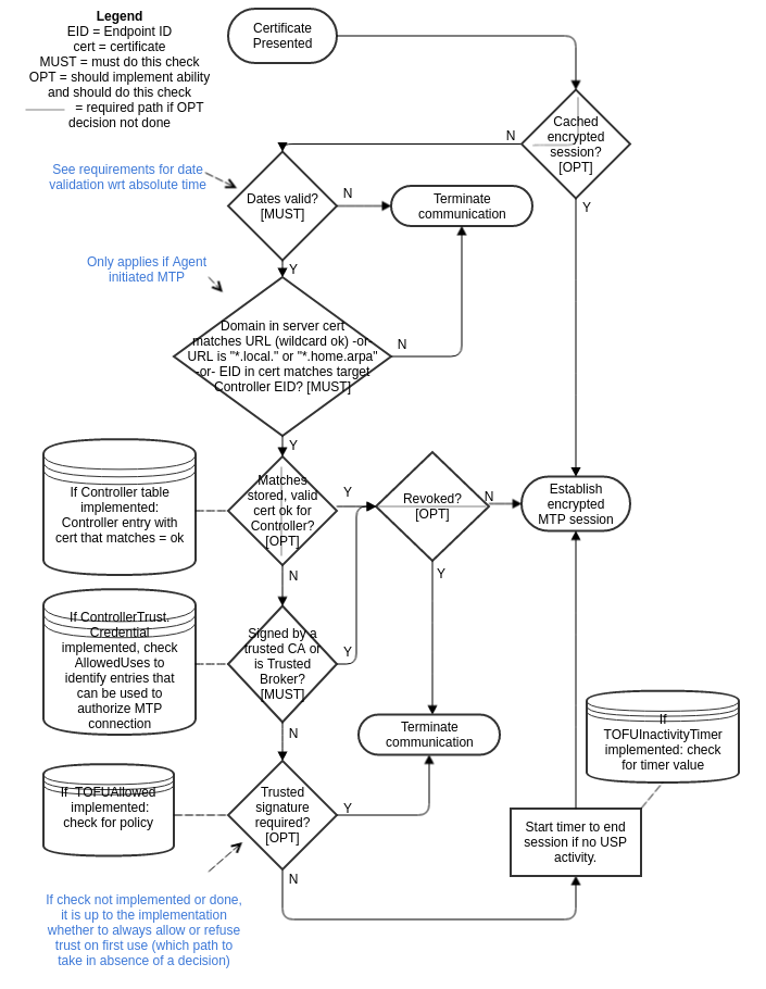
Note: The .local and .home.arpa domains are defined by the IETF as “Special-Use Domains” for use inside any LAN. It is not possible for an external Certificate Authority (CA) to vouch for whether a LAN device “owns” a particular name in one of these domains (inside a particular LAN) and these LAN networks have no internal CA. Therefore, it is not possible to validate FQDNs within these domains. The Internet Assigned Numbers Authority (IANA) maintains a registry of Special Use Domains.
4.1.3 USP Record Encapsulation
The USP Record is defined as the Message Transfer Protocol (MTP) payload, encapsulating a sequence of datagrams that comprise the USP Message as well as providing additional metadata needed for integrity protection, payload protection and delivery of fragmented USP Messages. Additional metadata fields are used to identify the E2E session context, determine the state of the segmentation and reassembly function, acknowledge received datagrams, request retransmissions, and determine the type of encoding and security mechanism used to encode the USP Message.
When not explicitly set or included in a USP Record or USP Message, the fields have a default value based on the type of field:
- For strings, the default value is the empty string.
- For bytes, the default value is empty bytes.
- For bools, the default value is
false. - For numeric types, the default value is zero.
- For enums, the default value is the first defined enum value, which must be 0.
- For a
oneoffield, none of the allowed values are assumed if the field is absent. repeatedfields can be included any number of times, including zero.
If there is no requirement stating a field must be present, it is not necessary to include the field in a sent Record or Message. The receiving Endpoint will use default values for fields not included in a received Record or Message.
R-MTP.4b - Any field that is noted as “Required” in its description MUST be sent.
A Record or Message without a required field will fail to be processed by a receiving Endpoint. For additional information, default values (when fields are missing) are described in the “Default Values” section of Protocol Buffers [4].
4.1.3.1 Record Definition
Note: This version of the specification defines the USP Record in Protocol Buffers v3. This part of the specification may change to a more generic description (normative and non-normative) if further encodings are specified in future versions.
string version
Required. Version (Major.Minor) of the USP Protocol (e.g., “1.3”).
Note: The version field is used for USP Endpoints to set expectations about their behavior for other USP Endpoints. A USP Endpoint that receives a Record indicating a version higher than it supports can expect to receive messages it may not understand or encounter other unexpected behavior. USP Endpoints are expected to handle these inconsistencies gracefully (For example, using the 7001 Message Not Supported Error).
string to_id
Required. Receiving/Target USP Endpoint Identifier.
string from_id
Required. Source USP Endpoint Identifier.
string originator_id
Optional. Originating USP Endpoint Identifier.
R-MTP.4c - A USP Endpoint that
receives a message that needs to be forwarded to another USP Endpoint
MUST populate the originator_id with the
from_id from the received message.
R-MTP.4d - A USP Endpoint that
receives a message where the originator_id is expected and
is either empty or not available MUST consider the from_id
to be the originator.
string destination_id
Optional. Destination USP Endpoint Identifier.
Some Events, e.g. Device.Bulkdata.Profile.{i}.Push!, are
sent only to the USP Controller that configured the source of the Event
(assuming it has an associated Subscription), even if another USP
Controller has an associated Subscription. In these cases, the data
model stores the identifier of the USP Controller that configured the
source of the Event. When a USP Endpoint emits a USP event, the
identifier of the USP Controller is communicated to other USP Endpoints
using the destination_id field of the USP record. This
enables the receiving USP Endpoint to determine which USP Controller
needs to receive the forwarded USP event.
R-MTP.4e A USP Agent that is
sending a Notify message containing an Event that is defined on a per
Controller basis (e.g., Device.BulkData., Device.LocalAgent.Monitor.,
and Device.LocalAgent.Threshold.) MUST populate the
destination_id field of the USP Record with the USP
Controller Endpoint ID associated with the Event.
enum PayloadSecurity payload_security
Optional. An enumeration of type PayloadSecurity. When the payload is
present, this indicates the protocol or mechanism used to secure the
payload (if any) of the USP Message. The value of TLS12
means TLS 1.2 or later (with backward compatibility to TLS 1.2) will be
used to secure the payload (see TLS Payload Encapsulation for more information).
Valid values are:
PLAINTEXT (0)
TLS12 (1)
bytes mac_signature
Optional. When integrity protection of non-payload fields is performed, this is the message authentication code or signature used to ensure the integrity of the non-payload fields of the USP Record.
bytes sender_cert
Optional. The PEM encoded certificate, or certificate chain, of the
sending USP Endpoint used to provide the signature in the
mac_signature field, when integrity protection is used and
the payload security mechanism doesn’t provide the mechanism to generate
the mac_signature.
oneof record_type
Required. This field contains one of the types given below:
NoSessionContextRecord no_session_context
SessionContextRecord session_context
WebSocketConnectRecord websocket_connect
MQTTConnectRecord mqtt_connect
STOMPConnectRecord stomp_connect
UDSConnectRecord uds_connect
DisconnectRecord disconnect
4.1.3.1.1 NoSessionContextRecord fields
The following describe the fields included if
record_type is no_session_context.
bytes payload
Required. The USP Message.
4.1.3.1.2 SessionContextRecord fields
The following describe the fields included if
record_type is session_context.
uint64 session_id
Required. This field is the Session Context identifier.
uint64 sequence_id
Required. Datagram sequence identifier. Used only for exchange of USP Records with an E2E Session Context. The field is initialized to 1 when starting a new Session Context and incremented after each sent USP Record.
Note: Endpoints maintain independent values for received and sent sequence_id for a Session Context, based respectively on the number of received and sent Records.
uint64 expected_id
Required. This field contains the next sequence_id the
sender is expecting to receive, which implicitly acknowledges to the
recipient all transmitted datagrams less than expected_id.
Used only for exchange of USP Records with an E2E Session Context.
uint64 retransmit_id
Optional. Used to request a USP Record retransmission by a USP
Endpoint to request a missing USP Record using the missing USP Record’s
anticipated sequence_id. Used only for exchange of USP
Records with an E2E Session Context. Will be received as 0
when no retransmission is requested.
enum PayloadSARState payload_sar_state
Optional. An enumeration of type PayloadSARState. When payload is present, indicates the segmentation and reassembly state represented by the USP Record. Valid values are:
NONE (0)
BEGIN (1)
INPROCESS (2)
COMPLETE (3)
enum PayloadSARState payloadrec_sar_state
Optional. An enumeration of type PayloadSARState. When payload
segmentation is being performed, indicates the segmentation and
reassembly state represented by an instance of the payload datagram. If
payload_sar_state = 0 (or is not included or
not set), then payloadrec_sar_state will be 0
(or not included or not set). Valid values are:
NONE (0)
BEGIN (1)
INPROCESS (2)
COMPLETE (3)
repeated bytes payload
Optional. This repeated field is a sequence of zero, one, or multiple
datagrams. It contains the Message, in either PLAINTEXT or
encrypted format. When using TLS12 payload security, this
contains the encrypted TLS records, either sequentially in a single
payload field, or divided into multiple
payload fields. When using PLAINTEXT payload
security there will be a single payload field for any
Message being sent.
4.1.3.1.3 WebSocketConnectRecord fields
This Record type has no fields.
4.1.3.1.4 MQTTConnectRecord fields
The following describe the fields included if
record_type is mqtt_connect.
enum MQTTVersion version
Required. The MQTT protocol version used by the USP Endpoint to send this Record. Valid values are:
V3_1_1 (0)
V5 (1)
string subscribed_topic
Required. A MQTT Topic where the USP Endpoint sending this Record can be reached (i.e. a non-wildcarded MQTT Topic it is subscribed to).
4.1.3.1.5 STOMPConnectRecord fields
The following describe the fields included if
record_type is stomp_connect.
enum STOMPVersion version
Required. The STOMP protocol version used by the USP Endpoint to send this Record. Valid values are:
V1_2 (0)string subscribed_destination
Required. A STOMP Destination where the USP Endpoint sending this Record can be reached (i.e. a STOMP Destination it is subscribed to).
4.1.3.1.6 UDSConnectRecord fields
This Record type has no fields.
4.1.3.1.7 DisconnectRecord fields
The following describe the fields included if
record_type is disconnect.
fixed32 reason_code
Optional. A code identifying the reason of the disconnect.
string reason
Optional. A string describing the reason of the disconnect.
4.1.4 USP Record Errors
A variety of errors can occur while establishing and during a USP communication flow. In order to signal such problems to the other Endpoint while processing an incoming E2E Session Context Record or a Record containing a Message of the type Request, an Endpoint encountering such a problem can create a USP Record containing a Message of type Error and transmit it over the same MTP and connection which was used when the error was encountered.
For this mechanism to work and to prevent information leakage, the sender causing the problem needs to be able to create a valid USP Record containing a valid source Endpoint ID and a correct destination Endpoint ID. In addition a MTP specific return path needs to be known so the error can be delivered.
R-MTP.5 - A recipient of an erroneous USP Record MUST create a Record with a Message of type Error and deliver it to sender if the source Endpoint ID is valid, the destination Endpoint ID is its own, the Record contains a USP Message of type Request, the Message ID can be extracted, and a MTP-specific return path is known. If any of those criteria on the erroneous Record are not met, it MUST be ignored.
The following error codes (in the range 7100-7199) are defined to allow the Error to be more specifically indicated. Additional requirements for these error codes are included in the specific MTP definition, where appropriate.
| Code | Name | Description |
|---|---|---|
7100 |
Record could not be parsed | This error indicates the received USP Record could not be parsed. |
7101 |
Secure session required | This error indicates USP layer Secure Message Exchange is required. |
7102 |
Secure session not supported | This error indicates USP layer Secure Message Exchange was indicated in the received Record but is not supported by the receiving Endpoint. |
7103 |
Segmentation and reassembly not supported | This error indicates segmentation and reassembly was indicated in the received Record but is not supported by the receiving Endpoint. |
7104 |
Invalid Record value | This error indicates the value of at least one Record field was invalid. |
7105 |
Session Context terminated | This error indicates an existing Session Context Establishing an E2E Session Context is being terminated. |
7106 |
Session Context not allowed | This error indicates use of Session Context Establishing an E2E Session Context is not allowed or not supported. |
4.1.5 Connect and Disconnect Record Types
A Connect Record is a subgroup of Record types
(record_type), there is one Record type per USP MTP in this
subgroup. These Records are used to assert the USP Agent presence and
exchange needed information for proper start of communication between
Agent and Controller, the presence information is specifically useful
when using brokered MTPs.
R-MTP.6 - If a USP Agent has the necessary information to create a Connect Record, it MUST send the associated Connect Record, specific for the MTP in use, after it has successfully established an MTP communications channel to a USP Controller.
The DisconnectRecord is a Record type used by a USP
Agent to indicate it wishes to end an on-going communication with a USP
Controller. It can be used for presence information, for sending
supplemental information about the disconnect event and to force the
remote USP Endpoint to purge some cached information about the current
session.
R-MTP.7 - The USP Agent SHOULD
send a DisconnectRecord to the USP Controller before
disconnecting from an MTP communications channel. Upon receiving a
DisconnectRecord, a USP Controller MUST clear all cached
information relative to an existing E2E Session Context with that
Endpoint, including the information that a previous E2E Session Context
was established.
It is not mandatory for a USP Endpoint to close its MTP connection
after sending or receiving a DisconnectRecord.
R-MTP.8 - After sending or
receiving a DisconnectRecord and maintaining the underlying
MTP communications channel or after establishing a new MTP
communications channel, the USP Endpoint MUST send or receive the
correct Connect Record type before exchanging any other USP Records.
R-MTP.9 - A
DisconnectRecord SHOULD include the
reason_code and reason fields with an
applicable code from USP Record Errors.
4.2 CoAP Binding (OBSOLETED)
Note: The CoAP MTP was deprecated in USP 1.2. Due to the way it is specified this MTP can only be used in local area networks under narrow conditions. Please see Section 4.3 for a suitable alternative.
Note: The CoAP MTP was obsoleted in USP 1.3 as a natural progression from being deprecated in USP 1.2.
The Constrained Application Protocol (CoAP) MTP transfers USP Records between USP Endpoints using the CoAP protocol as defined in RFC 7252 [29]. Messages that are transferred between CoAP clients and servers utilize a request/response messaging interaction based on RESTful architectural principles. The following figure depicts the transfer of the USP Records between USP Endpoints.
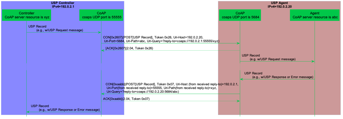
In this example, a USP Request is encoded within a USP Record and encapsulated within a CoAP request message. When a USP Endpoint receives the CoAP request message the USP Endpoint immediately sends a CoAP response message (with no USP Record) to indicate receipt of the message. A USP Response encoded within a USP Record is encapsulated in a new CoAP request message. When the USP Endpoint receives the USP Response, it sends a CoAP response message that indicates receipt of the message. Therefore, all Endpoints supporting CoAP will implement both CoAP client and server.
As noted in the definition of a USP Request, this USP Record either requests the Agent perform some action (create, update, delete, operate, etc.), requests information about an Agent or one or more Service Elements, or acts as a means to deliver Notifications from the Agent to the Controller. Notifications will only cause a USP Response to be generated if specified in the Notification Request. However, the CoAP response will always be sent.
4.2.1 Mapping USP Endpoints to CoAP URIs
Section 6 of RFC 7262 [29] discusses the URI schemes for identifying CoAP resources and provides a means of locating the resource. These resources are organized hierarchically and governed by a CoAP server listening for CoAP requests on a given port. USP Endpoints are one type of CoAP resource that is identified and discovered.
R-COAP.0 - As the USP Endpoint is a resource governed by a CoAP server, the CoAP server MUST also be identified as defined in section 6 of RFC 7262 [29].
R-COAP.1 - A USP Endpoint MUST be represented as a CoAP resource with the following resource attributes:
- Identifier within the CoAP server (uri-path)
- Resource type (rt): “
bbf.usp.endpoint” - Interface (if): “
bbf.usp.c” for USP Controller or “bbf.usp.a” for USP Agent
The identifier within the CoAP server is used to deliver messages to the USP Endpoint. When this identifier is used to deliver messages to the USP Endpoint, this identifier is a uri-path that represents the USP Endpoint.
R-COAP.2 - A CoAP request message
MUST include a Uri-Query option that supplies the CoAP server URI of the
Endpoint that is the source of the CoAP request, formatted as
?reply-to=<coap or coaps uri>. The coap and coaps
URIs are defined in sections 6.1 and 6.2 of RFC 7262 [29]. The URI MUST NOT include any
optional queries at the end.
R-COAP.2a - When a USP Endpoint receives a CoAP request message it MUST use the reply-to Uri-Query option included in the CoAP request as the CoAP URI for the USP Response (if a response is required by the incoming USP Request).
R-COAP.3 - When creating DNS-SD records (see DNS-SD Records), an Endpoint MUST set the DNS-SD TXT record “path” attribute equal to the value of the CoAP server identifier (uri-path).
4.2.2 Mapping USP Records to CoAP Messages
R-COAP.4 - In order for USP Records to be transferred between a USP Controller and Agent using CoAP, the USP Record MUST be encapsulated within the CoAP message as defined in RFC 7262 [29].
R-COAP.5 – USP Records that exceed the CoAP message size MUST be block encapsulated in accordance with [32].
USP Records are transferred using the CoAP resource that represents the receiving USP Endpoint using the CoAP POST method as defined in RFC 7252.
R-COAP.6 - The CoAP Content-Format for USP Records MUST be application/octet-stream (ID=42) for Message Encoding.
R-COAP.7 - Upon successful
reception of the CoAP message using POST, the CoAP server MUST respond
with a response code of 2.04 (Changed).
4.2.2.1 Handling CoAP Request Failures
At times CoAP requests fail to complete due to problems in the underlying transport (e.g., timeout) or a failure response code received from the CoAP server due to problems in the CoAP request sent by the CoAP client (4.xx) or problems with the CoAP server implementation (5.xx).
R-COAP.8 - CoAP clients and servers MUST implement the required CoAP response codes defined in section 5.9 of RFC 7262 [29].
R-COAP.9 - When a CoAP client receives a failure indication (e.g., timeout) from the underlying transport layer, the CoAP client MUST indicate a timeout to the USP Endpoint.
R-COAP.10 - When a CoAP client receives a response code of 4.xx or 5.xx, the CoAP client MUST indicate a CoAP failure to the USP Endpoint.
When a CoAP client sends a CoAP request, the CoAP client can provide incorrect or missing information in the CoAP request. For example, a CoAP client can send a CoAP request with an:
- Invalid CoAP method: The CoAP server responds with a
4.05 - Invalid Content-Format options: The CoAP server responds with a
4.15 - Invalid or not understandable payload: The CoAP server responds with
a
4.00
R-COAP.11 - When a CoAP server
receives a CoAP request with an invalid CoAP method, the CoAP server
MUST respond with a 4.05 response code.
R-COAP.12 - When a CoAP server
receives a CoAP request with an invalid CoAP Content-Format option, the
CoAP server MUST respond with a 4.15 response code.
R-COAP.13 - When a CoAP server
receives a CoAP request and the receiving USP Endpoint cannot interpret
or decode the USP Record for processing, the CoAP server MUST respond
with a 4.00 response code.
4.2.3 MTP Message Encryption
CoAP MTP message encryption is provided using DTLS as described in Section 9 of RFC 7262 [29].
In section 9 of RFC 7262 [29], CoAP messages are secured using one of three modes:
- NoSec: DTLS is disabled
- PreSharedKey: DTLS is enabled and the MTP endpoint uses pre-shared keys that are used to validate the identity of CoAP endpoints involved in the message exchange
- RawPublicKey: DTLS is enabled and the MTP endpoint has an asymmetric key pair without a certificate. The MTP endpoint has an identity calculated from the public key and a list of other MTP endpoints to which it can communicate
- Certificate: DTLS is enabled and the MTP endpoint has an asymmetric key pair with an X.509 certificate.
R-COAP.14 - CoAP clients and servers MUST implement the NoSec and Certificate modes of CoAP security as defined in RFC 7262 [29].
While section 9 of RFC 7262 [29] provides guidance on securing CoAP, further guidance related to DTLS implementations for the Internet of Things is provided by RFC 7925 [31].
R-COAP.15 - CoAP clients and servers MUST implement the mandatory statements of RFC 7925 [31] with the exception that:
- Section 4.4.1 USP Controller certificates can contain domain names with wildcard characters per RFC 6125 [22] guidance.
- Section 4.4.2 Client certificate identifiers do not use EUI-64 identifier but instead use the identifier defined for Client certificates in this Working Text.
- Section 4.4.5 Client Certificate URLs are not required to be implemented.
As USP Endpoints play the role of both CoAP client and server; when the MTP is secured using the Certificate mode of CoAP Security, the USP Endpoint provides a X.509 certificate to the MTP peer.
R-COAP.16 – When the Certificate mode of CoAP is used to secure an MTP, a USP Endpoint MUST provide an X.509 certificate to the MTP peer.
Note that DTLS sessions established for an Endpoint’s CoAP client and CoAP server are distinct. Therefore, it is possible for CoAP to be encrypted in one direction and not the other. If this happens, the requirements and flows in Authentication and Authorization will dictate that Secure Message Exchange be used.
4.3 WebSocket Binding
The WebSockets MTP transfers USP Records between USP Endpoints using the WebSocket protocol as defined in RFC 6455 [23]. Messages that are transferred between WebSocket clients and servers utilize a request/response messaging interaction across an established WebSocket session.
4.3.1 Mapping USP Endpoints to WebSocket URIs
Section 3 of RFC 6455 discusses the URI schemes for identifying WebSocket origin servers and their target resources. These resources are organized hierarchically and governed by a WebSocket origin server listening for WebSocket messages on a given port. USP Endpoints are one type of WebSocket resource that is identified and discovered.
R-WS.1 - As the USP Endpoint is a resource governed by a WebSocket origin server, the WebSocket server MUST also be identified as defined in section 3 of RFC 6455 [23].
R-WS.2 - A USP Endpoint MUST be represented as a WebSocket resource using the path component as defined in section 3 of RFC 6455 [23].
R-WS.3 - When creating DNS-SD records (see Discovery), an Endpoint MUST set the DNS-SD TXT record “path” attribute equal to the value of the Websocket resource using the path component as defined in section 3 of RFC 6455 [23].
4.3.2 Handling of the WebSocket Session
When exchanging the USP Records across WebSockets MTPs, the two USP Endpoints establish a WebSocket session. These WebSocket sessions are expected to be long lived and are reused for subsequent USP Record exchange. A WebSocket session is established using a handshake procedure described in section 4 of RFC 6455. When a WebSocket connection is not longer necessary, the WebSocket connection is closed according to section 7 of RFC 6455. The following figure depicts a WebSocket session handshake that is originated by an Agent.
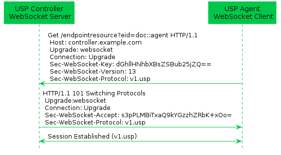
While WebSocket sessions can be established by either USP Controllers or USP Agents in many deployment scenarios (e.g. communication between USP Endpoints across the Internet), in general, USP Agents will establish the WebSocket session and not expose an open port toward the Internet for security reasons. Regardless of which entity establishes the WebSocket session, at most one (1) open WebSocket session is utilized between the USP Endpoints.
R-WS.4 - Any two (2) USP Endpoints that exchange USP Records MUST utilize at most one (1) open WebSocket session.
R-WS.5 - USP Agent MUST provide the capability to originate the establishment of a WebSocket session.
R-WS.6 - USP Agent MUST provide the capability to accept the establishment of a WebSocket session from a USP Controller.
Note: Requirement R-WS.6 was altered from a MAY to a MUST in USP 1.2 to ensure that the WebSocket MTP is suitable for the in-home communications use case.
R-WS.7 - A USP Endpoint MUST implement the WebSocket handshake protocol to establish a WebSocket connection as defined in section 4 of RFC 6455 [23].
R-WS.8 - A USP Endpoint MUST implement the procedures to close a WebSocket connection as defined in section 7 of RFC 6455 [23].
4.3.2.1 Mapping USP Records to WebSocket Messages
During the establishment of the WebSocket session, the WebSocket
client informs the WebSocket server in the
Sec-WebSocket-Protocol header about the type of USP Records
that will be exchanged across the established WebSocket connection. For
USP Records, the Sec-WebSocket-Protocol header contains the
value v1.usp. When presented with a
Sec-WebSocket-Protocol header containing
v1.usp, the WebSocket Server serving a USP Endpoint returns
v1.usp in the response’s Sec-WebSocket-Protocol header. If
the WebSocket client doesn’t receive a
Sec-WebSocket-Protocol header with a value of
v1.usp, the WebSocket client does not establish the
WebSocket session.
When a WebSocket connection is being initiated with TLS, no USP
Record is sent until the TLS negotiation is complete. The WebSocket
server will be unable to identify the Endpoint ID of the client unless
it looks inside the certificate. To make it easier for the server to
identify the client, the request URI of the opening handshake contains a
key=value pair in its query component to
provide the Endpoint ID of the client. eid is used as the
key to the pair, while the value is the Endpoint ID of the client,
e.g. eid=doc::agent.
Note: USP Endpoint IDs can contain percent-encoded characters,
which can create confusion when encoding it for URI use. The Endpoint ID
needs to be treated as opaque data for it to be properly “roundtripable”
when encoded/decoded for URI use, thus any percent character needs to be
percent-encoded, e.g. doc::agent%21 will be encoded as
doc::agent%2521.
R-WS.9 - The WebSocket’s
handshake Sec-WebSocket-Protocol header for exchange of USP
Records using the protocol-buffers encoding mechanism MUST be
v1.usp.
R-WS.10 - A WebSocket client MUST
include the Sec-WebSocket-Protocol header for exchange of
USP Records when initiating a WebSocket session.
R-WS.10a (DEPRECATED) - A
WebSocket client MUST include the Sec-WebSocket-Extensions
header with bbf-usp-protocol WebSocket Extension and
extension parameter eid equal to the client’s Endpoint ID
when initiating a WebSocket session.
Note: Requirement R-WS.10a was removed in USP 1.3, due to the impossibility of setting WebSocket Extensions in some environments.
R-WS.10b - A WebSocket client
MUST include its Endpoint ID, via a key=value pair, in the
query component of the request URI in its opening handshake, defined in
section 1.3 of RFC 6455 [23]. The
key part of the pair MUST have a value of eid
and the value part MUST be the client’s Endpoint ID. This
pair MUST be separated from other query data by the &
character.
R-WS.10c - When encoding the USP
Endpoint ID for URI use, it MUST be treated as opaque data and any
percent character MUST itself be percent-encoded, i.e. as
%25.
R-WS.11 - A WebSocket server that
supports USP Endpoints MUST include the
Sec-WebSocket-Protocol header for exchange of USP Records
when responding to an initiation of a WebSocket session.
R-WS.11a - A WebSocket server
SHOULD include the Sec-WebSocket-Extensions header with
bbf-usp-protocol WebSocket Extension and extension
parameter eid equal to the server’s Endpoint ID when
responding to an initiation of a WebSocket session that includes the
bbf-usp-protocol extension.
R-WS.11b - WebSocket clients MUST
NOT consider WebSocket responses that do not include the
bbf-usp-protocol WebSocket Extension to be an error.
R-WS.11c - WebSocket servers MUST
NOT consider WebSocket session initiation requests that do not include
the bbf-usp-protocol WebSocket Extension to be an
error.
R-WS.12 - A WebSocket client MUST
NOT establish a WebSocket session if the response to a WebSocket session
initiation request does not include the
Sec-WebSocket-Protocol header for exchange of USP Records
in response to an initiation of a WebSocket session.
R-WS.12a - A WebSocket server
MUST NOT establish a WebSocket session if the WebSocket session
initiation request does not include the
Sec-WebSocket-Protocol header.
4.3.3 Handling of WebSocket Frames
RFC 6455 defines a number of type of WebSocket control frames (e.g., Ping, Pong, Close) and associated condition codes in order to maintain a WebSocket connection. In addition messages are transferred in WebSocket Data control frame.
R-WS.13 - A USP Endpoint MUST implement the WebSocket control frames defined in section 5.5 of RFC 6455 [23].
USP Records can be transferred between USP Controllers and USP Agents over an established WebSocket session. These USP Records are encapsulated within a binary WebSocket data frame as depicted by the figure below. WebSocket message fragmentation should be avoided, because its main benefit does not apply for the case of sending USP Records.
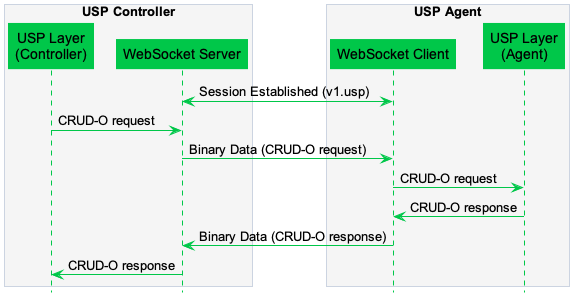
R-WS.14 - In order for USP Records to be transferred between a USP Controller and Agent using WebSockets MUST be encapsulated within as a binary WebSocket data frame as defined in section 5.6 of RFC 6455 [23].
R-WS.14a - USP Endpoints SHOULD NOT use WebSocket message fragmentation for sending USP Records.
R-WS.14b - USP Endpoints MUST support WebSocket message fragmentation in received USP Records.
R-WS.15 - USP Records are transferred between USP Endpoints using message body procedures as defined in section 6 of RFC 6455 [23].
4.3.3.1 Handling Failures to Deliver USP Records
If a USP Endpoint receives a WebSocket frame containing a USP Record
that cannot be extracted for processing (e.g., text frame instead of a
binary frame, malformed USP Record or USP Record, bad encoding), the
receiving USP Endpoint notifies the originating USP Endpoint that an
error occurred by closing the WebSocket connection with a
1003 Status Code with the WebSocket Close frame.
R-WS.16 - A USP Endpoint that
receives a WebSocket frame containing a USP Record that cannot be
extracted for processing, the receiving USP Endpoint MUST terminate the
connection using a WebSocket Close frame with a Status Code of
1003.
4.3.3.2 Keeping the WebSocket Session Alive
Once a WebSocket session is established, the WebSocket session is expected to remain open for future exchanges of USP Records. The WebSocket protocol uses Ping and Pong control frames as a keep-alive session. Section 5.5 of RFC 6455 discusses the handling of Ping and Pong control frames.
R-WS.17 - A USP Agent MUST implement a WebSocket keep-alive mechanism by periodically sending Ping control frames and responding to received Ping control frames with Pong control frames as described in section 5.5 of RFC 6455 [23].
R-WS.18 - A USP Agent MUST provide the capability to assign a keep-alive interval in order to send Ping control frames to the remote USP Endpoint.
4.3.3.3 WebSocket Session Retry
If for any reason a WebSocket Session is closed, the USP Endpoint will attempt to re-establish the WebSocket Session according to its session retry policy. For Controllers, this session retry policy is implementation specific.
R-WS.19 – When retrying to establish a WebSocket Session, the Agent MUST use the following retry algorithm to manage the WebSocket Session establishment procedure:
For Agents, the retry interval range is controlled by two variables (described in the table below): the minimum wait interval and the interval multiplier. The corresponding data model Parameter MAY be implemented to allow a USP Controller to change the values of these variables. The factory default values of these variables MUST be the default values listed in the Default column of the table below.
| Descriptive Name | Symbol | Default | Data Model Parameter Name |
|---|---|---|---|
| Minimum wait interval | m | 5 seconds | Device.LocalAgent.Controller.{i}.MTP.{i}.WebSocket.SessionRetryMinimumWaitInterval |
| Interval multiplier | k | 2000 | Device.LocalAgent.Controller.{i}.MTP.{i}.WebSocket.SessionRetryIntervalMultiplier |
| Retry Count | Default Wait Interval Range (min-max seconds) | Actual Wait Interval Range (min-max seconds) |
|---|---|---|
| #1 | 5-10 | m - m.(k/1000) |
| #2 | 10-20 | m.(k/1000) - m.(k/1000)^2 |
| #3 | 20-40 | m.(k/1000)^2 - m.(k/1000)^3 |
| #4 | 40-80 | m.(k/1000)^3 - m.(k/1000)^4 |
| #5 | 80-160 | m.(k/1000)^4 - m.(k/1000)^5 |
| #6 | 160-320 | m.(k/1000)^5 - m.(k/1000)^6 |
| #7 | 320-640 | m.(k/1000)^6 - m.(k/1000)^7 |
| #8 | 640-1280 | m.(k/1000)^7 - m.(k/1000)^8 |
| #9 | 1280-2560 | m.(k/1000)^8 - m.(k/1000)^9 |
| #10 and subsequent | 2560-5120 | m.(k/1000)^9 - m.(k/1000)^10 |
R-WS.20 – Once a WebSocket session is established between the Agent and the Controller, the Agent MUST reset the WebSocket MTP’s retry count to zero for the next WebSocket Session establishment.
R-WS.21 – If a reboot of the Agent occurs, the Agent MUST reset the WebSocket MTP’s retry count to zero for the next WebSocket Session establishment.
4.3.4 MTP Message Encryption
WebSocket MTP message encryption is provided using certificates in TLS as described in section 10.5 and section 10.6 of RFC 6455 [23].
R-WS.22 - USP Endpoints utilizing WebSockets clients and servers for message transport MUST implement the Certificate modes of TLS security as defined in sections 10.5 and 10.6 of RFC 6455 [23].
R-WS.23 - USP Endpoints capable of obtaining absolute time SHOULD wait until it has accurate absolute time before contacting the peer USP Endpoint. If a USP Endpoint for any reason is unable to obtain absolute time, it can contact the peer USP Endpoint without waiting for accurate absolute time. If a USP Endpoint chooses to contact the peer USP Endpoint before it has accurate absolute time (or if it does not support absolute time), it MUST ignore those components of the peer USP Endpoint’s WebScoket MTP certificate that involve absolute time, e.g. not-valid-before and not-valid-after certificate restrictions.
R-WS.24 - USP Controller certificates MAY contain domain names with wildcard characters per RFC 6125 [22] guidance.
4.4 STOMP Binding
The STOMP MTP transfers USP Records between USP endpoints using version 1.2 of the STOMP protocol [41], further referred to as “STOMP Specification”, or the Simple Text Oriented Message Protocol. Messages that are transferred between STOMP clients utilize a message bus interaction model where the STOMP server is the messaging broker that routes and delivers messages based on the destination included in the STOMP header.
The following figure depicts the transfer of the USP Records between USP Agents and Controllers.
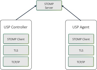
The basic steps for any USP Endpoint that utilizes a STOMP MTP are:
- Negotiate TLS (if required/configured)
- Connect to the STOMP Server
- Maintain Heart Beats (if configured)
- Subscribe to a Destination
- Send USP Records
R-STOMP.0 - USP Agents utilizing
STOMP clients for message transport MUST support the
STOMPConn:1 and STOMPController:1 data model
profiles.
R-STOMP.1 - USP Agents utilizing
STOMP clients for message transport SHOULD support the
STOMPAgent:1 and STOMPHeartbeat:1 data model
profile.
4.4.1 Handling of the STOMP Session
When exchanging USP Records across STOMP MTPs, each USP Endpoint establishes a communications session with a STOMP server. These STOMP communications sessions are expected to be long lived and are reused for subsequent exchange of USP Records. A STOMP communications session is established using a handshake procedure as described in “Connecting a USP Endpoint to the STOMP Server” section below. A STOMP communications session is intended to be established as soon as the USP Endpoint becomes network-aware and is capable of sending TCP/IP messages.
When a STOMP communications session is no longer necessary, the STOMP
connection is closed by the STOMP client, preferably by sending a
DISCONNECT frame (see “Handling Other STOMP Frames” section
below).
4.4.1.1 Connecting a USP Endpoint to the STOMP Server
R-STOMP.2 - USP Endpoints
utilizing STOMP clients for message transport MUST send a
STOMP frame to the STOMP server to initiate the STOMP
communications session as defined in the “Connecting” section of the
STOMP Specification.
R-STOMP.3 - USP Endpoints that DO
NOT utilize client certificate authentication MUST include the login and
passcode STOMP headers in the STOMP frame. For a USP Agent, if the
.STOMP.Connection.{i}.Username Parameter is implemented
then its value will be the source for the login STOMP
header, and if the .STOMP.Connection.{i}.Password Parameter
is implemented then its value will be the source for the
passcode STOMP header.
R-STOMP.4 - USP Endpoints sending
a STOMP frame MUST include (in addition to other mandatory
STOMP headers) an endpoint-id STOMP header containing the
Endpoint ID of the USP Endpoint sending the frame. Note: According
to the STOMP Specification, the STOMP frame requires that
“C style literal escapes” need to be used to encode any carriage return,
line feed, or colon characters that are found within the UTF-8 encoded
headers, and R-STOMP.4
requires the Endpoint ID to be included in those headers. Since the
Endpoint ID always contains colon characters, those will need to be
escaped.
R-STOMP.5 - USP Endpoints sending
a STOMP frame MUST include a host STOMP header, if configured to do so.
For a USP Agent the value MUST contain the value from the appropriate
.STOMP.Connection.{i}.VirtualHost Parameter if supported
and not empty.
R-STOMP.6 - If the USP Endpoint
receives a subscribe-dest STOMP header in the
CONNECTED frame, it MUST use the associated value when
Subscribing to its destination (see “Subscribing a USP Endpoint to a
STOMP Destination” section for more details).
R-STOMP.7 - If the connection to
the STOMP server is NOT successful then the USP Endpoint MUST enter a
connection retry state. For a USP Agent the retry mechanism is based on
the STOMP.Connection.{i}. retry Parameters:
ServerRetryInitialInterval,
ServerRetryIntervalMultiplier, and
ServerRetryMaxInterval.
4.4.1.2 Handling the STOMP Heart Beat Mechanism
The STOMP Heart Beat mechanism can be used to periodically send data between a STOMP client and a STOMP server to ensure that the underlying TCP connection is still available. This is an optional STOMP mechanism and is negotiated when establishing the STOMP connection.
R-STOMP.8 - If the
STOMP.Connection instance’s EnableHeartbeats
Parameter value is true then the USP Agent MUST negotiate the STOMP
Heart Beat mechanism within the STOMP frame during the
process of establishing the STOMP connection as is defined in the
“Heart-beating” section of the STOMP Specification.
R-STOMP.9 - If the
STOMP.Connection instance’s EnableHeartbeats
Parameter value is either false or not implemented then the USP Agent
MUST either not send the heart-beat STOMP header in the
STOMP frame or send “0,0” as the value of the
heart-beat STOMP header in the STOMP
frame.
R-STOMP.10 - USP Agents
negotiating the STOMP Heart Beat mechanism MUST use the
STOMP.Connection.{i}.OutgoingHeartbeat and
STOMP.Connection.{i}.IncomingHeartbeat Parameter values
within the heart-beat STOMP header as defined in the
“Heart-beating” section of the STOMP Specification.
R-STOMP.11 - USP Agents that have
negotiated a STOMP Heart Beat mechanism with a STOMP server MUST adhere
to the heart beat values (as defined in the “Heart-beating” section of
the STOMP Specification) as returned in the CONNECTED
frame.
4.4.2 Mapping USP Endpoints to STOMP Destinations
USP Agents will have one STOMP destination per STOMP MTP independent
of whether those STOMP MTPs use the same STOMP.Connection
instance or a different one. The STOMP destination is either configured
by the STOMP server via the USP custom subscribe-dest STOMP
Header received in the CONNECTED frame (exposed in the
Device.LocalAgent.MTP.{i}.STOMP.DestinationFromServer
Parameter) or taken from the
Device.LocalAgent.MTP.{i}.STOMP.Destination Parameter if
there wasn’t a subscribe-dest STOMP Header received in the
CONNECTED frame. The USP custom subscribe-dest
STOMP Header is helpful in scenarios where the USP Agent doesn’t have a
pre-configured destination as it allows the USP Agent to discover the
destination.
A USP Controller will subscribe to a STOMP destination for each STOMP
server that it is associated with. The USP Controller’s STOMP
destination needs to be known by the USP Agent (this is configured in
the
Device.LocalAgent.Controller.{i}.MTP.{i}.STOMP.Destination
Parameter) as it is used when sending a USP Record containing a
Notification.
4.4.2.1 Subscribing a USP Endpoint to a STOMP Destination
R-STOMP.12 - USP Endpoints
utilizing STOMP clients for message transport MUST subscribe to their
assigned STOMP destination by sending a SUBSCRIBE frame to
the STOMP server as defined in the “SUBSCRIBE” section of the STOMP
Specification.
R-STOMP.13 - USP Endpoints
sending a SUBSCRIBE frame MUST include (in addition to
other mandatory STOMP headers) a destination STOMP header
containing the STOMP destination associated with the USP Endpoint
sending the frame.
R-STOMP.14 - USP Agents that
receive a subscribe-dest STOMP Header in the
CONNECTED frame MUST use that STOMP destination in the
destination STOMP header when sending a
SUBSCRIBE frame.
R-STOMP.15 - USP Agents that have
NOT received a subscribe-dest STOMP Header in the
CONNECTED frame MUST use the STOMP destination found in the
Device.LocalAgent.MTP.{i}.STOMP.Destination Parameter in
the destination STOMP header when sending a
SUBSCRIBE frame.
R-STOMP.16 - USP Agents that have
NOT received a subscribe-dest STOMP Header in the
CONNECTED frame and do NOT have a value in the
Device.LocalAgent.MTP.{i}.STOMP.Destination Parameter MUST
terminate the STOMP communications session (preferably via the
DISCONNECT frame) and enter a connection retry state
following R-STOMP.7.
R-STOMP.17 - USP Endpoints
sending a SUBSCRIBE frame MUST use an ack
value of “auto”.
4.4.3 Mapping USP Records to STOMP Frames
A USP Record is sent from a USP Endpoint to a STOMP Server within a
SEND frame. The STOMP Server delivers that USP Record to
the destination STOMP Endpoint within a MESSAGE frame. When
a USP Endpoint responds to the USP request, the USP Endpoint sends the
USP Record to the STOMP Server within a SEND frame, and the
STOMP Server delivers that USP Record to the destination USP Endpoint
within a MESSAGE frame.
R-STOMP.18 - USP Endpoints
utilizing STOMP clients for message transport MUST send USP Records in a
SEND frame to the STOMP server as defined in the “SEND”
section of the STOMP Specification.
R-STOMP.19 - USP Endpoints
sending a SEND frame MUST include (in addition to other
mandatory STOMP headers) a content-length STOMP header
containing the length of the body included in the SEND
frame.
R-STOMP.20 - USP Endpoints
sending a SEND frame MUST include (in addition to other
mandatory STOMP headers) a content-type STOMP header with a
value of “application/vnd.bbf.usp.msg”, which signifies
that the body included in the SEND frame contains a
Protocol Buffer [4] binary encoding
message.
R-STOMP.21 - USP Endpoints
sending a SEND frame with content-type of
application/vnd.bbf.usp.msg MUST include (in addition to
other mandatory STOMP headers) a reply-to-dest STOMP header
containing the STOMP destination that indicates where the USP Endpoint
that receives the USP Record should send any response (if required).
R-STOMP.22 - USP Endpoints
sending a SEND frame with content-type of
application/vnd.bbf.usp.msg MUST include the Protocol
Buffer [4] binary encoding
of the USP Record as the body of the SEND frame.
R-STOMP.23 - When a USP Endpoint
receives a MESSAGE frame it MUST use the
reply-to-dest included in the STOMP headers as the STOMP
destination of the USP response (if a response is required by the
incoming USP request).
4.4.3.1 Handling Errors
If a STOMP USP Endpoint receives a MESSAGE frame
containing a USP Record that cannot be extracted for processing (e.g.,
text frame instead of a binary frame, malformed USP Record, bad
encoding), it will silently drop the unprocessed USP Record. If the
requirements according to USP Record Errors are fulfilled, for the STOMP MTP
specifically this means that the reply-to-dest information
has to be available, then a USP Record with an appropriate Error Message
must be created and transmitted via STOMP SEND frame.
Note: Error handling was unified between MTPs in USP 1.2 by using USP Records instead of MTP specific messages, deprecating most of this section, specifically the requirements R-STOMP.23a, R-STOMP.23b, R-STOMP.24, R-STOMP.24a and R-STOMP.24b. Please see USP Record Errors for details.
R-STOMP.23a (DEPRECATED) - USP
Endpoints MUST support STOMP content-type header value of
application/vnd.bbf.usp.error.
Note: Requirement R-STOMP.23a was removed in USP 1.2
R-STOMP.23b (DEPRECATED) - A USP
Endpoint MUST include a usp-err-id STOMP header in
SEND frames of content-type
application/vnd.bbf.usp.msg. The value of this header is:
<USP Record to_id> + "/" + <USP Message msg_id>,
the <USP Message msg_id> field can be left blank if
the Record does not contain a USP Message. Since the colon
“:” is a reserved character in STOMP headers, all instances
of “:” in the USP Record to_id MUST be expressed using an
encoding of \c.
Note: Requirement R-STOMP.23b was removed in USP 1.2
R-STOMP.24 (DEPRECATED) - When a
USP Endpoint receives a MESSAGE frame containing a USP
Record or an encapsulated USP Message within a USP Record that cannot be
extracted for processing, the receiving USP Endpoint MUST ignore the USP
Record if the received STOMP MESSAGE frame did not include a
usp-err-id header.
Note: Requirement R-STOMP.24 was removed in USP 1.2
R-STOMP.24a (DEPRECATED) - When a
USP Endpoint receives a MESSAGE frame containing a USP Record or an
encapsulated USP Message within a USP Record that cannot be extracted
for processing, the receiving USP Endpoint MUST send a STOMP SEND frame
with an application/vnd.bbf.usp.error content-type header
value if the received STOMP MESSAGE frame included a
usp-err-id header.
Note: Requirement R-STOMP.24a was removed in USP 1.2
R-STOMP.24b (DEPRECATED) - A
STOMP SEND frame with application/vnd.bbf.usp.error
content-type MUST contain the received usp-err-id header,
the destination header value set to the received
reply-to-dest header, and a message body (formatted using
UTF-8 encoding) with the following 2 lines:
err_code:<numeric code indicating the type of error that caused the overall message to fail>err_msg:<additional information about the reason behind the error>
The specific error codes are listed in the MTP USP Record Errors section.
The following is an example message. This example uses
“^@” to represent the NULL octet that follows a STOMP
body.
SEND
destination:/usp/the-reply-to-dest
content-type:application/vnd.bbf.usp.error
usp-err-id:cid\c3AA3F8\cusp-id-42/683

err_code:7100
err_msg:Field n is not recognized.^@
Note: Requirement R-STOMP.24b was removed in USP 1.2
R-STOMP.25 - If an
ERROR frame is received by the USP Endpoint, the STOMP
server will terminate the connection. In this case the USP Endpoint MUST
enter a connection retry state. For a USP Agent the retry mechanism is
based on the STOMP.Connection.{i}. retry Parameters:
ServerRetryInitialInterval,
ServerRetryIntervalMultiplier, and
ServerRetryMaxInterval.
4.4.3.2 Handling Other STOMP Frames
R-STOMP.26 - USP Endpoints
utilizing STOMP clients for message transport MUST NOT send the
transactional STOMP frames including: BEGIN,
COMMIT, and ABORT.
R-STOMP.27 - USP Endpoints
utilizing STOMP clients for message transport MUST NOT send the
acknowledgement STOMP frames including: ACK and
NACK.
R-STOMP.28 - USP Endpoints
utilizing STOMP clients for message transport MAY send the following
STOMP frames when shutting down a STOMP connection:
UNSUBSCRIBE (according to the rules defined in the
UNSUBSCRIBE section of the STOMP Specification) and
DISCONNECT (according to the rules defined in the
DISCONNECT section of the STOMP Specification).
R-STOMP.29 - USP Endpoints
utilizing STOMP clients for message transport that DID NOT receive a
subscribe-dest STOMP Header in the CONNECTED
frame when establishing the STOMP communications session MUST update
their STOMP subscription when their destination is altered by sending
the UNSUBSCRIBE STOMP frame (according to the rules defined
in the UNSUBSCRIBE section of the STOMP Specification) and then
re-subscribing as detailed in the “Subscribing a USP Endpoint to a STOMP
Destination” section.
R-STOMP.30 - USP Endpoints
utilizing STOMP clients for message transport MAY receive a
RECEIPT frame in which case the STOMP server is
acknowledging that the corresponding client frame has been processed by
the server.
4.4.4 Discovery Requirements
The USP Discovery section details requirements about the general usage of DNS, mDNS, and DNS-SD records as it pertains to the USP protocol. This section provides further requirements as to how a USP Endpoint advertises discovery information when a STOMP MTP is being utilized.
R-STOMP.31 - When creating a
DNS-SD record, an Endpoint MUST set the DNS-SD “path”
attribute equal to the value of the destination that it has subscribed
to.
R-STOMP.32 - When creating a DNS-SD record, an Endpoint MUST utilize the STOMP server’s address information in the A and AAAA records instead of the USP Endpoint’s address information.
4.4.5 STOMP Server Requirements
R-STOMP.33 - A STOMP server implementation MUST adhere to the requirements defined in the STOMP Specification.
R-STOMP.34 - A STOMP server implementation MUST perform authentication of the STOMP client and ensure that a Remote USP Endpoint is only allowed to subscribe to the destination that is associated with the USP Endpoint.
R-STOMP.35 - A STOMP server implementation SHOULD support both Client Certification Authentication and Username/Password Authentication mechanisms.
4.4.6 MTP Message Encryption
STOMP MTP message encryption is provided using certificates in TLS as described in section 10.5 and section 10.6 of RFC 6455 [23].
R-STOMP.36 - USP Endpoints utilizing STOMP clients for message transport MUST implement TLS 1.2 RFC 5246 [18] or later with backward compatibility to TLS 1.2.
R-STOMP.37 - STOMP server certificates MAY contain domain names and those domain names MAY contain domain names with wildcard characters per RFC 6125 [22] guidance.
4.5 MQTT Binding
The Message Queuing Telemetry Transport (MQTT) MTP transfers USP Records between USP Endpoints using the MQTT protocol. Messages that are transferred between MQTT clients utilize a message bus interaction model where the MQTT server is the messaging broker that routes and delivers messages based on the Topic Name included in the MQTT Publish packet variable header.
The following figure depicts the transfer of the USP Records between USP Agents and Controllers.
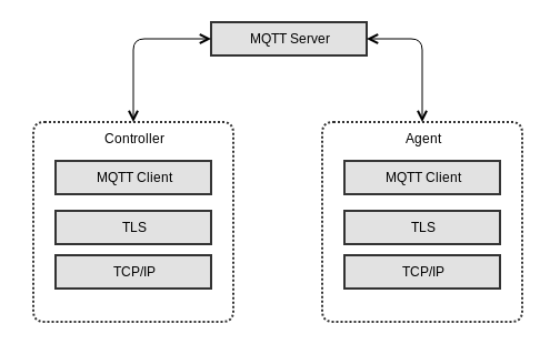
The basic steps for any USP Endpoint that utilizes an MQTT MTP are:
- Negotiate TLS (if required/configured)
- Connect to the MQTT Server (server may require Authentication)
- Subscribe to a Topic
- Publish USP Records
- Optionally send
PINGREQmessages to keep the connection alive
The following figure shows the MQTT packets that have requirements in this section for their use when MQTT is a USP MTP.
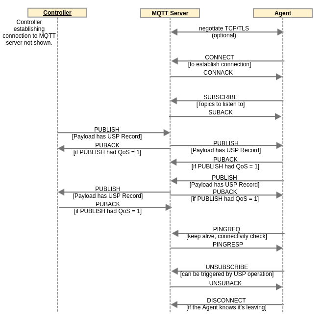
R-MQTT.1 - USP Endpoints utilizing MQTT clients for message transport MUST implement MQTT 5.0 [38].
R-MQTT.2 - USP Endpoints utilizing MQTT clients for message transport MAY implement MQTT 3.1.1 [37].
Requirements in this MQTT MTP specification are common to both the MQTT 3.1.1 and MQTT 5.0 specifications unless an MQTT version is named.
The MQTT specifications are very complete and comprehensive in describing syntax and usage requirements of MQTT packets and behaviors. Therefore, none of those requirements are re-iterated in this specification. This specification only contains requirements unique to use of MQTT as a USP MTP. The above two requirements for compliance with the MQTT specifications are critical in developing an implementation compliant with this MQTT Binding specification. Wherever an MQTT packet or other functionality is mentioned in the requirements in this MQTT Binding specification, the requirement for compliance with the MQTT specification (R-MQTT.1 and R-MQTT.2) apply.
R-MQTT.3 - USP Agents utilizing MQTT clients for message transport MUST support MQTT over TCP transport protocol.
The MQTT specification also describes how MQTT can run over WebSockets. Deployments can choose to use MQTT over WebSockets, if they use MQTT clients and servers with support for this option. The TCP option is required to ensure interoperability.
R-MQTT.4 - USP Agents utilizing
MQTT clients for message transport MUST support the
MQTTClientCon:1, MQTTClientSubscribe:1,
MQTTAgent:1, and MQTTController:2 data model
profiles.
R-MQTT.5 - USP Agents utilizing
MQTT clients for message transport SHOULD support the
MQTTClientExtended:1 data model profile.
4.5.1 Connecting a USP Endpoint to the MQTT Server
When exchanging USP Records across MQTT MTPs, each USP Endpoint establishes a communications session with an MQTT server. These MQTT communications sessions are expected to be long-lived and are re-used for subsequent exchange of USP Records. An MQTT communications session is established using the procedure in this section. An MQTT communications session is intended to be established as soon as the USP Endpoint becomes network-aware and can send TCP/IP messages.
When an MQTT communications session is no longer necessary or expires
(see “Keep Alive” section below), the MQTT connection is closed by the
MQTT client, preferably by sending a DISCONNECT packet (see
Handling
Other MQTT Packets section below).
R-MQTT.1 and R-MQTT.2 require that all MQTT
capabilities referenced in this section and its sub-sections are
compliant with the MQTT specifications. Reading the MQTT specification
is highly recommended to ensure the correct syntax and usage of MQTT
packets and properties (CONNECT, CONNACK, User
Name, Password, ClientId, User Property, Keep Alive,
PINGREQ, PINGRESP, etc.).
R-MQTT.6 - USP Endpoints
utilizing MQTT clients for message transport MUST send a
CONNECT packet to the MQTT server to initiate the MQTT
communications session.
R-MQTT.7 - USP Endpoints with a
configured MQTT User Name and Password for use with this MQTT server
MUST include these in the MQTT CONNECT packet. The
.MQTT.Client.{i}.Username and
.MQTT.Client.{i}.Password Parameter values (associated with
this MQTT server) will be used for User Name and Password.
R-MQTT.8 - USP Endpoints MUST set
the value of the CONNECT packet Client Identifier
(ClientId) as follows:
- If a non-empty, non-null ClientId value exists for use with this
MQTT server, this MUST be used. The data model Parameter for the
ClientId is
.MQTT.Client.{i}.ClientID. - If an MQTT 5.0 client has no configured ClientId (null or empty string) the USP Endpoint MUST send an empty string in the Client Identifier property.
- If an MQTT 3.1.1 client has no configured ClientId, the USP Endpoint SHOULD attempt to use its USP Endpoint ID as the ClientId.
R-MQTT.9 - An MQTT 5.0 client
MUST save (in the .MQTT.Client.{i}.ClientID Parameter) an
Assigned Client Identifier included in a CONNACK packet as
its configured ClientId for future connections to the MQTT server.
R-MQTT.10 - If the connection to
the MQTT server is NOT successful then the USP Endpoint MUST enter a
connection retry state. For a USP Agent the retry mechanism is based on
the MQTT.Client.{i}. retry Parameters:
ConnectRetryTime,
ConnectRetryIntervalMultiplier, and
ConnectRetryMaxInterval.
R-MQTT.11 - Once a USP Endpoint has successfully connected to an MQTT server, it MUST use the same ClientId for all subsequent connections with that server.
4.5.1.1 CONNECT Flags and Properties
The MQTT CONNECT packet has a number of flags and
properties that can be set. The User Name and Password flags are set to
1 if these parameters are included. The use of the Will Retain, Will
QoS, and Will Flag are left up to the deployment. They are not needed in
order to use MQTT as a USP MTP and can be “0” if there is no
deployment-specified need for them. The Clean Start flag can also be
used according to deployment-specified needs. Configured values for
these flags can be provided through the related
.MQTT.Client.{i}. Parameters.
MQTT 3.1.1 does not provide a simple mechanism for a USP MQTT client to provide its Endpoint ID to the MQTT server. But the server does have other options, such as:
- Support Endpoint ID as ClientId.
- Get Endpoint ID from client TLS certificate.
MQTT 3.1.1 also does not provide a mechanism for the MQTT server to tell a client what Topic other Endpoints should use to send the client a message (the “reply to” Topic). This information would need to be pre-configured or provided in some manner not specified here.
MQTT 5.0 includes additional properties that deployments can choose to use.
R-MQTT.12 - An MQTT 5.0 USP
Endpoint MUST support setting the Request Response Information property
to 1, and MUST support receiving the corresponding Response Information
in the CONNACK packet.
The Response Information property is used by an MQTT 5.0 client as
the Response Topic (which is the MQTT 5.0 PUBLISH packet
property identifying the Topic to send a USP response to). The Response
Information property requirements for use of the received Response
Information are below in Sending the USP Record in a PUBLISH Packet Payload.
Ensuring the client is subscribed to this Topic or a Topic Filter that
includes this Topic is described in Subscribing to
MQTT Topics.
R-MQTT.13 - An MQTT 5.0 USP
Endpoint MUST include a User Property name-value pair in the
CONNECT packet with name of “usp-endpoint-id” and value of
this Endpoint’s USP Endpoint ID.
4.5.1.2 Keep Alive
The MQTT Keep Alive mechanism has several components:
- The
CONNECTpacket Keep Alive field tells the server to disconnect the client if the server does not receive a packet from the client before the Keep Alive time (in seconds) has elapsed since the prior received packet. - The MQTT 5.0
CONNACKpacket Keep Alive field allows the server to inform the client the maximum interval the server will allow to elapse between received packets before it disconnects the client due to inactivity. PINGREQandPINGRESPpackets can be used to keep the connection up if the timer is nearing expiry and there is no need for another type of message.PINGREQcan also be used by the client at any time to check on the status of the connection.
The client can indicate the Server is not required to disconnect the
Client on the grounds of inactivity by setting the CONNECT
Keep Alive to zero (0). Note that WebSockets mechanisms can be used to
keep the connection alive if MQTT is being run over WebSockets. Also
note the server is allowed to disconnect the client at any time,
regardless of Keep Alive value.
R-MQTT.14 - USP Endpoints with a
configured Keep Alive value MUST include this in the MQTT
CONNECT packet. The
.MQTT.Client.{i}.KeepAliveTime Parameter value (associated
with this MQTT server) will be used for the Keep Alive value.
Use of PINGREQ and PINGRESP for keeping
sessions alive (or determining session aliveness) is as described in the
MQTT specification. No additional requirements are provided for use of
these packets in a USP context.
4.5.2 Subscribing to MQTT Topics
The SUBSCRIBE packet is sent by the MQTT client to
subscribe to one or more Topics or Topic Filters. These are needed to
allow the MQTT client to receive application messages. The MQTT client
will receive all application messages published by other clients that
are sent to a Topic that matches (either exactly or within a wildcarded
Topic Filter) a subscribed-to Topic or Topic Filter. The MQTT server
indicates in the SUBACK response packet whether the client
has succeeded or failed to subscribe to each Topic or Topic Filter sent
in the SUBSCRIBE packet.
USP Endpoints can be configured with one or more specific MQTT Topics
or Topic Filters to subscribe to for each MQTT server they are
associated with. In MQTT 5.0, a CONNACK User Property named
“subscribe-topic” can be used to provide the client with Topic or Topic
Filter values for the client to subscribe to. There is no similar
capability in MQTT 3.1.1. This means configuration or some out-of-band
mechanism are the only means of supplying subscription Topics or Topic
Filters to an MQTT 3.1.1 client. An Agent will need to be configured
with a Controller’s MQTT Topic (the
Device.LocalAgent.Controller.{i}.MTP.{i}.MQTT.Topic
Parameter is used to configure this), to send a Notification to that
Controller.
R-MQTT.1 and R-MQTT.2 require that all MQTT
capabilities referenced in this section and its sub-sections are
compliant with the MQTT specifications. Reading the MQTT specification
is highly recommended to ensure the correct syntax and usage of MQTT
packets and properties (SUBSCRIBE, Topic Filter, QoS 0, QoS
1, QoS 2, etc.).
R-MQTT.15 - USP Endpoints that
successfully connect to an MQTT server MUST send a
SUBSCRIBE packet with all Topic Filters identified in the
following list:
- All configured Topic Filter values for use with this MQTT server
MUST be included in a
SUBSCRIBEpacket. For a USP Agent, the.MQTT.Client.{i}.Subscription.{i}.table can be used to configure Topic Filter values. - If an MQTT 5.0 USP Endpoint received one or more User Property in
the
CONNACKpacket where the name of the name-value pair is “subscribe-topic”, the USP Endpoint MUST include the value of all such name-value pairs in itsSUBSCRIBEpacket as a Topic Filter. - If an MQTT 5.0 Endpoint received a Response Information property in
the
CONNACKpacket, and the topic from that Response Information property is not included (directly or as a subset of a Topic Filter) among the Topic Filters of the previous 2 bullets, the Endpoint MUST include the value of the Response Information property in itsSUBSCRIBEpacket. - If a USP Agent has a
ResponseTopicConfiguredvalue and did not receive a Response Information property in theCONNACKpacket, and the topic in theResponseTopicConfiguredParameter is not included (directly or as a subset of a Topic Filter) among the Topic Filters of the first 2 bullets, the Agent MUST include the value of theResponseTopicConfiguredin itsSUBSCRIBEpacket. For MQTT 5.0 clients, the subscription topic is set to the value ofResponseTopicConfigured. For MQTT 3.1.1 clients, the subscription topic is set to a wildcarded topic filter based on the value ofResponseTopicConfigured.
R-MQTT.16 - USP Agents that have
NOT received any Subscriptions outlined in R-MQTT.15 “subscribe-topic” User Property in the
CONNACK and do NOT have a configured Topic Filter
(Device.MQTT.Client.{i}.Subscription.{i}.Topic Parameter
for this Client instance in the data model) MUST terminate the MQTT
communications session (via the DISCONNECT packet) and
consider the MTP disabled.
R-MQTT.17 - If a USP Endpoint does not successfully subscribe to at least one Topic, it MUST NOT publish a packet with a USP Record in its Application Message, and MUST disconnect from the MQTT server.
For each Topic listed in a SUBSCRIBE packet, the client
will also provide a desired QoS level. See the MQTT specification (MQTT
3.1.1 [37] or MQTT 5.0
[38], Section 4.3) for description of
the three QoS levels (QoS 0, QoS 1, QoS 2). The usefulness of these QoS
levels in the context of USP depends on the particulars of the MQTT
deployment. It is therefore up to the implementer / deployer to decide
which QoS setting to use. In order to ensure deployments have the
ability to use at least QoS 1, MQTT clients and servers are required to
implement at least QoS 1 (see requirements in Sending the USP Record in a PUBLISH Packet Payload
and MQTT Server
Requirements).
4.5.3 Sending the USP Record in a PUBLISH Packet Payload
A USP Record is sent from a USP Endpoint to an MQTT Server within a
PUBLISH packet payload. The MQTT Server delivers that
PUBLISH packet to the destination MQTT client USP Endpoint.
This is true of all USP Message types.
R-MQTT.1 and R-MQTT.2 require that all MQTT
capabilities referenced in this section and its sub-sections are
compliant with the MQTT specifications. Reading the MQTT specification
is highly recommended to ensure the correct syntax and usage of MQTT
packets and properties (PUBLISH, Content Type, Response
Topic, etc.).
R-MQTT.18 - USP Endpoints
utilizing MQTT clients for message transport MUST send the USP Record in
the payload of a PUBLISH packet.
R-MQTT.19 - USP Endpoints MUST send USP Records using the Protocol Buffer [4] binary encoding of the USP Record.
R-MQTT.20 - USP Endpoints utilizing MQTT clients for message transport MUST support MQTT QoS 0 and QoS 1.
The USP Controller’s MQTT Topic needs to be known by any USP Agent expected to send a Notify message to the Controller.
The USP Agent will also need to know an exact Topic where it can be reached (and not just a Topic Filter) in order to provide a Controller with the Agent’s “reply to” Topic.
R-MQTT.21 - An MQTT 5.0 USP
Endpoint that receives Response Information in the CONNACK
packet MUST use this as its “reply to” Topic.
Note: By using a single “reply to” Topic for all USP connections, an Agent on the MQTT server may become a DoS attack vector and cannot be unsubscribed from because this would cause the Agent to lose all “reply to” traffic.
R-MQTT.22 - USP Endpoints MUST
include a “reply to” Topic in all PUBLISH packets
transporting USP Records.
R-MQTT.23 - USP Endpoints using
MQTT 5.0 MUST include their “reply to” Topic in the PUBLISH
Response Topic property.
R-MQTT.24 - USP Endpoints using
MQTT 3.1.1 MUST include their “reply to” Topic after “/reply-to=” at the
end of the PUBLISH Topic Name, with any “/” character in
the Topic replaced by “%2F”.
For example, if a Controller’s “reply to” Topic is
“usp/controllers/oui:00256D:my-unique-bbf-id-42”, and it is sending to
an Agent whose Topic is “usp/agents/cid:3AA3F8:my-unique-usp-id-42”, the
PUBLISH Topic Name for a USP Controller using an MQTT 3.1.1
client will be “usp/agents/cid:3AA3F8:my-unique-usp-id-42/reply-to=
usp%2Fcontrollers%2Foui:00256D:my-unique-bbf-id-42”.
USP Endpoints that need to send a response to a received USP Record
will need to determine the Topic Name to use in the responding
PUBLISH packet.
R-MQTT.25 - USP Endpoints using
MQTT 3.1.1 MUST interpret the portion of the received
PUBLISH Topic Name following the last forward slash
“/reply-to=” as the response Topic Name. Any instance of “%2F” in this
received string MUST be replaced with “/”.
R-MQTT.26 - USP Endpoints using
MQTT 5.0 MUST use the received PUBLISH Response Topic
property as the response Topic Name.
When an USP Endpoint receives a MQTT 3.1.1 PUBLISH
packet without “reply to” Topic or a USP Connect Record
with a different MQTT version indicated in the version
field of the mqtt_connect Record type, then a MQTT version
mismatch between brokers involved in the MQTT communication has
occurred.
R-MQTT.26a - If a MQTT version mismatch is encountered and the sender “reply to” Topic is known, the receiving Endpoint MUST handle this error according to Handling Errors and cease communication until the mismatch has been addressed by the sender.
R-MQTT.27 - USP Endpoints sending a USP Record using MQTT 5.0 MUST have “usp.msg” in the Content Type property.
MQTT clients using MQTT 3.1.1 will need to know to pass the payload
to the USP Agent for handling. There is no indication in MQTT 3.1.1 of
the payload application or encoding. an MQTT 3.1.1 deployment could
choose to dedicate the MQTT connection to USP, or put something in the
syntax of PUBLISH packet Topic Names that would indicate
the payload is a USP Record.
R-MQTT.27a - USP Endpoints
receiving a MQTT 5.0 PUBLISH packet MUST interpret the
Content Type property of “usp.msg” or “application/vnd.bbf.usp.msg” (the
registered USP Record MIME type) as indicating the packet contains a USP
Record.
4.5.4 Handling Errors
The MQTT specification requires servers and clients to disconnect if there is a violation at the MQTT protocol layer.
If a MQTT USP Endpoint receives a PUBLISH packet
containing a USP Record that cannot be extracted for processing
(e.g. malformed USP Record or bad encoding), it will silently drop the
unprocessed USP Record. If the requirements according to USP Record Errors are
fulfilled, then a USP Record with an appropriate Error Message will be
created and published.
Note: Error handling was unified between MTPs in USP 1.2 by using USP Records instead of MTP specific messages, deprecating most of this section, specifically R-MQTT.28, R-MQTT.29, R-MQTT.30, R-MQTT.31, R-MQTT.31a and R-MQTT.32. Please see USP Record Errors for details.
R-MQTT.28 (DEPRECATED) - MQTT 5.0
Endpoints MUST support PUBLISH Content Type value of
“usp.error”.
Note: Requirement R-MQTT.28 was removed in USP 1.2
R-MQTT.29 (DEPRECATED) - MQTT 5.0
Endpoints MUST include a usp-err-id MQTT User Property in
PUBLISH packets of content-type “usp.msg”. The value of
this User Property is:
<USP Record to_id> + "/" + <USP Message msg_id>,
the <USP Message msg_id> field can be left blank if
the Record does not contain a USP Message.
Note: Requirement R-MQTT.29 was removed in USP 1.2
R-MQTT.30 (DEPRECATED) - When an
MQTT 3.1.1 USP Endpoint receives a PUBLISH packet
containing a USP Record or an encapsulated USP Message within a USP
Record that cannot be extracted for processing, the receiving USP
Endpoint MUST silently drop the USP Record.
Note: Requirement R-MQTT.30 was removed in USP 1.2
R-MQTT.31 (DEPRECATED) - When an
MQTT 5.0 USP Endpoint receives a PUBLISH packet containing
a USP Record or an encapsulated USP Message within a USP Record that
cannot be extracted for processing and the PUBLISH packet
contains a usp-err-id header, the receiving USP Endpoint
MUST send a PUBLISH packet with Content Type “usp.error”, a
User Property set to the received usp-err-id User Property,
the Topic Name set to the received Response Topic, and a
PUBLISH Payload (formatted using UTF-8 encoding) with the
following 2 lines:
err_code:<numeric code indicating the type of error that caused the overall message to fail>err_msg:<additional information about the reason behind the error>
The specific error codes are listed in the MTP USP Record Errors section.
MQTT 5.0 includes a Reason Code that is used to respond to
PUBLISH packets when QoS 1 or QoS 2 is used.
Note: Requirement R-MQTT.31 was removed in USP 1.2
R-MQTT.31a (DEPRECATED) - USP
Endpoints receiving a MQTT 5.0 PUBLISH packet MUST
interpret the Content Type property of “usp.error” or
“application/vnd.bbf.usp.error” (the registered USP error message MIME
type) as indicating the packet contains a USP error message and
code.
Note: Requirement R-MQTT.31a was removed in USP 1.2
R-MQTT.32 (DEPRECATED) - When a
USP Endpoint using MQTT 5.0 receives a PUBLISH packet with
QoS 1 or QoS 2 containing a USP Record or an encapsulated USP Message
within a USP Record that cannot be extracted for processing, the
receiving USP Endpoint MUST include Reason Code 153 (0x99) identifying
“Payload format invalid” in any PUBACK or
PUBREC packet.
Note these packets will be received by the MQTT server and will not be forwarded to the USP Endpoint that originally sent the USP Record.
Note: Requirement R-MQTT.32 was removed in USP 1.2
R-MQTT.33 - If the MQTT server
terminates the connection, the USP Endpoint MUST enter a connection
retry state. For a USP Agent the retry mechanism is based on the
MQTT.Client.{i}. ConnectRetryTime Parameter.
4.5.5 Handling Other MQTT Packets
Use of PUBREL, and PUBCOMP depends on the
QoS level being used for the subscribed Topic. No additional
requirements are provided for use of these packets in a USP context.
Use of PINGREQ and PINGRESP for keeping
sessions alive (or determining session aliveness) is as described in the
MQTT specification. No additional requirements are provided for use of
these packets in a USP context.
Use of UNSUBSCRIBE and UNSUBACK is as
described in the MQTT specification. If an Agent’s configured Topics are
disabled by a Controller (by setting
Device.MQTT.Client.{i}.Subscription.{i}.Enable to “false”),
UNSUBSCRIBE is used to unsubscribe from them.
R-MQTT.34 - USP Endpoints
utilizing MQTT clients for message transport SHOULD send an
UNSUBSCRIBE packet when a subscribed Topic or Topic Filter
is no longer indicated but the MQTT connection is expected to stay
up.
R-MQTT.1 and R-MQTT.2 require that all MQTT
capabilities referenced in this section and its sub-sections are
compliant with the MQTT specifications. Reading the MQTT specification
is highly recommended to ensure the correct syntax and usage of MQTT
packets and properties (DISCONNECT, etc.).
R-MQTT.35 - USP Endpoints
utilizing MQTT clients for message transport SHOULD send a
DISCONNECT packet when shutting down an MQTT
connection.
MQTT 5.0 specifies the AUTH packet to use for extended
authentication. Implementations can make use of extended authentication
but should only do so if they are sure that all clients and servers will
support the same authentication mechanisms.
4.5.6 Discovery Requirements
The USP discovery section details requirements about the general usage of DNS, mDNS, and DNS-SD records as it pertains to the USP protocol. This section provides further requirements as to how a USP Endpoint advertises discovery information when an MQTT MTP is being utilized.
R-MQTT.36 - When creating a DNS-SD record (DNS-SD Records), an Agent MUST set the DNS-SD “path” attribute equal to the value of its “reply to” Topic.
R-MQTT.37 - When creating a DNS-SD record (DNS-SD Records), a Controller MUST set the DNS-SD “path” attribute equal to a value that is included among the Controller’s subscribed Topics and Topic Filters.
R-MQTT.38 - When creating a DNS-SD record, an Endpoint MUST utilize the MQTT server’s address information in the A and AAAA records instead of the USP Endpoint’s address information.
4.5.7 MQTT Server Requirements
R-MQTT.39 - MQTT servers MUST implement MQTT 5.0 [38].
R-MQTT.40 - MQTT servers SHOULD implement MQTT 3.1.1 [37].
R-MQTT.41 - MQTT servers MUST implement MQTT over TCP transport protocol.
R-MQTT.42 - An MQTT server MUST support authentication of the MQTT client through at least one of the mechanisms described in Section 5.4.1 of the MQTT specification, and support an Access Control List mechanism that can restrict the topics an authenticated MQTT client can subscribe or publish to.
R-MQTT.43 - An MQTT server SHOULD support both Client Certification Authentication and User Name / Password Authentication mechanisms.
R-MQTT.44 - An MQTT server SHOULD
support sending Topic or Topic Filter values in a “subscribe-topic” User
Property in the CONNACK packet.
R-MQTT.45 - If an MQTT server supports subscriptions from unconfigured Agents, it MUST support wildcarded Topic Filters.
This will allow support for Agents that try to subscribe to “+/<Endpoint ID>/#” and “+/+/<Endpoint ID>/#” Topic Filters.
R-MQTT.46 - An MQTT server MUST support at least MQTT QoS 1 level.
R-MQTT.47 - An MQTT server SHOULD support a ClientId value that is a USP Endpoint ID. This includes supporting all Endpoint ID characters (includes “-”, “.”, “_”, “%”, and “:”) and at least 64 characters length.
4.5.8 MTP Message Encryption
MQTT MTP message encryption is provided using certificates in TLS as described in section 10.5 and section 10.6 of RFC 6455 [23].
R-MQTT.48 - USP Endpoints utilizing MQTT clients for message transport MUST implement TLS 1.2 [18] or later with backward compatibility to TLS 1.2.
R-MQTT.48a - USP Endpoints
utilizing MQTT clients for message transport SHOULD support
Application-Layer Protocol Negotiation (ALPN) extensions as
defined in [30] as part of the
TLS handshake.
R-MQTT.49 - MQTT server certificates MAY contain domain names and those domain names MAY contain domain names with wildcard characters per RFC 6125 [22] guidance.
4.6 UNIX Domain Socket Binding
This is an internal Message Transfer Protocol (MTP) for communicating between a USP Agent and a USP Controller that reside on separate processes within a single device. This MTP uses UNIX domain sockets to send Frames between the UNIX domain socket clients and servers. The Frame contains a Header field and one or more Type-Length-Value (TLV) fields to transport USP Records and other information related to the use of this transport as a USP MTP.
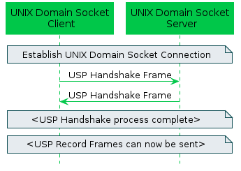
4.6.1 Handling UNIX Domain Socket Connections
UNIX domain socket concepts are broken down into two key aspects: server and client. A UNIX domain socket server is responsible for listening on an UNIX domain socket for incoming connections and then accepting those connections such that the server can then send and receive messages over the connection. A UNIX domain socket client is responsible for establishing a connection to a server such that the client can then send and receive messages over the established communications session.
UNIX domain sockets are different than other sockets as they aren’t governed by a host and port. Instead, the UNIX domain socket is associated to a local file path (and its internal file descriptor).
A USP Agent communicating over UNIX domain sockets as the USP MTP can act as either a UNIX domain socket server or a UNIX domain socket client, but not both.
A USP Controller communicating over UNIX domain sockets as the USP MTP can act as either a UNIX domain socket server or a UNIX domain socket client, but not both.
Since UNIX domain sockets and this type of internal MTP is completely contained within the device itself, there is no need to advertise the USP Agent or USP Controller details via mDNS.
R-UDS.1 - USP Agents utilizing UNIX domain socket servers or clients for message transport MUST support the UDSAgent:1 and UDSController:1 data model profiles.
4.6.1.1 Establishing a UNIX Domain Socket Connection
This section contains requirements related to setting up a UNIX domain socket connection between a USP Agent and a USP Controller that reside on two separate processes within the same device.
R-UDS.2 - A USP Endpoint acting as a UNIX domain socket server MUST bind to a UNIX domain socket and listen for incoming connections.
R-UDS.3 - A USP Endpoint acting as a UNIX domain socket server MUST accept incoming connections from UNIX domain socket clients.
To get to this point, a connection to the server’s listen socket must be made from the USP Endpoint acting as a UNIX domain socket client.
R-UDS.4 - A USP Endpoint acting as a UNIX domain socket client MUST connect to a known UNIX domain socket server using a SOCK_STREAM connection.
At this point we have a bidirectional UNIX domain socket connection, which can be used to send USP Records between a USP Agent and a USP Controller.
4.6.1.2 Retrying a UNIX Domain Socket Connection
UNIX domain sockets don’t often get disconnected after the connection has been established on both ends, but there are cases where a retry algorithm is valuable:
- Many UNIX domain socket clients are simultaneously attempting to establish a connection with the UNIX domain socket server, and that limit exceeds the “backlog” value that the UNIX domain socket server used when calling the “listen” system call.
- A UNIX domain socket is terminated by the USP Agent or USP Controller due to some failure to deliver or handle a frame message (see Section 4.6.2.1 Handling Failures to Handshake, Section 4.6.3.1 Handling Failures to Deliver USP Records, Section 4.6.5 Handling Other UNIX Domain Socket Failures, and Section 4.6.6 Error Handling)
If for any reason a UNIX domain socket connection fails to be established or is closed, the USP Endpoint acting as a client will attempt to re-establish the UNIX domain socket connection.
R-UDS.5 - When a UNIX domain socket connection is closed or fails to be established, the USP Endpoint acting as a client MUST attempt to re-establish the UNIX domain socket within a random amount of time between 1 and 5 seconds.
4.6.1.3 Sending a Message over a UNIX Domain Socket
This MTP uses UNIX domain sockets to send Frames between the UNIX domain socket clients and servers. The UNIX domain socket Frame contains a Header field and one or more Type-Length-Value (TLV) fields to transport the information related to the use of this transport as a USP MTP. The Header field contains a Synchronization part (which includes the hexadecimal version of “_USP”) and a Length part that contains the length of the remainder of the Frame (i.e. the length of the entire Frame excluding the size of the Header). The Type part of the TLV field will always be 1 byte, the Length part of the TLV field will always be 4 bytes, and the Value part of the TLV field is based on the Type.
R-UDS.6 - A Frame sent across a UNIX domain socket that is being used as an MTP MUST have a Header field and one or more TLV fields.
R-UDS.7 - The Header of a Frame sent across a UNIX domain socket that is being used as an MTP MUST have a synchronization part and a length part.
R-UDS.8 - The synchronization portion of the Frame’s Header MUST contain the following 4 bytes: 0x5f 0x55 0x53 0x50 (the hexadecimal version of “_USP”).
R-UDS.9 - The length portion of the Frame’s Header MUST contain the length of the remainder of the Frame (i.e. the length of the entire Frame excluding the size of the Header) as a 4 byte unsigned integer in network byte order.
R-UDS.10 - A TLV field contained in a Frame sent across a UNIX domain socket that is being used as an MTP MUST have a 1 byte Type.
R-UDS.11 - A TLV field contained in a Frame sent across a UNIX domain socket that is being used as an MTP MUST have a 4 byte Length in network byte order.
The following set of Types are defined as allowable types in the TLV fields:
| Type | Name | Description of Value |
|---|---|---|
1 |
Handshake | The Handshake contains a UTF-8 string that represents the Endpoint ID of the USP Endpoint sending the message. |
2 |
Error | The Error contains a UTF-8 string that provides the error message related to the communications failure. |
3 |
USP Record | The USP Record contains the Google Protocol Buffer binary-encoded USP Record being sent between a USP Agent and USP Controller. |
4 |
Password | The password contains a UTF-8 string that represents the shared secret associated with the USP Endpoint sending the message |
R-UDS.12 - A Frame sent across a UNIX domain socket that is being used as an MTP MUST contain a TLV with Type 1 for any Handshake negotiation messages
R-UDS.13 - A Frame sent across a UNIX domain socket that is being used as an MTP MUST contain a TLV with Type 2 for any Error messages
R-UDS.14 - A Frame sent across a UNIX domain socket that is being used as an MTP MUST contain a TLV with Type 3 for any USP Record messages
R-UDS.15 - A Frame sent across a UNIX domain socket that is being used as an MTP MUST ignore any TLVs that have unexpected Types
4.6.2 Handshaking with UNIX Domain Sockets
After a UNIX domain socket is established between a server (either a USP Agent acting as a server or a USP Controller acting as a server) and a client (either a USP Agent acting as a client or a USP Controller acting as a client), the USP Endpoints need to exchange Handshake Frames to provide each other with their identities because every USP Record contains the from and to Endpoint ID. This means that both the USP Agent and USP Controller will send a Frame with a Type 1 TLV and their own Endpoint ID before sending any USP Record across the newly established UNIX domain socket connection.
R-UDS.16 - A USP Endpoint acting as a UNIX domain socket client MUST send a Unix domain socket Frame containing a Type 1 (Handshake) TLV field, and optionally a Type 4 (Password )TLV field, once it establishes a UNIX domain socket connection. This message MUST contain the Endpoint ID of the USP Endpoint sending the message, and optionally its associated password.
R-UDS.17 - A USP Endpoint acting as a UNIX domain socket server MUST send a Unix domain socket Frame containing a Type 1 (Handshake) TLV field once it receives a Unix domain socket Frame containing a Type 1 (Handshake) TLV field, and optionally a Type 4 (Password) TLV field, from a USP Endpoint acting as a UNIX domain socket client. This message MUST contain the Endpoint ID of the USP Endpoint sending the message, and optionally its associated password.
R-UDS.18 - A USP Endpoint acting as a UNIX domain socket client MUST terminate the UNIX domain socket connection if it doesn’t receive a Unix domain socket Frame containing a Type 1 (Handshake) TLV field within 30 seconds of when it sent its own Unix domain socket Frame containing a Type 1 (Handshake) TLV field.
Once both sides of the UNIX domain socket have successfully completed the handshake process, which is done by the USP Agent and the USP Controller exchanging Unix domain socket Frames that contain a Type 1 (Handshake) TLV field, and optionally a Type 4 (Password) TLV field, then either the USP Agent or USP Controller may begin sending USP Record messages.
R-UDS.19 - A USP Endpoint acting as a UNIX domain socket client or server MUST ignore an unexpected UNIX domain socket Frame that contains a Type 1 (Handshake) TLV field.
R-UDS.20 - A USP Endpoint acting as a UNIX domain socket client or server MUST ignore any UNIX domain socket Frames that contain a Type 3 (USP Record) TLV field until it has successfully completed the handshake process.
The following image shows an example of a UNIX domain socket Frame that contains a Type 1 (Handshake) TLV field used for handshaking between a USP Agent and USP Controller. In this example, the Endpoint ID being used is “os::00256D-0123456789”.
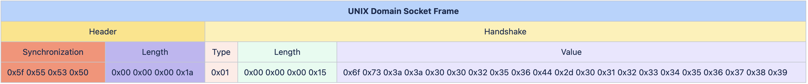
The following image shows an example of a UNIX domain socket Frame that contains a Type 4 (Handshake with shared secret) TLV field used for handshaking between a USP Agent and USP Controller. In this example, the Endpoint ID being used is “os::00256D-0123456789” and a shared secret of “xxxxxxxxxxxxx”.
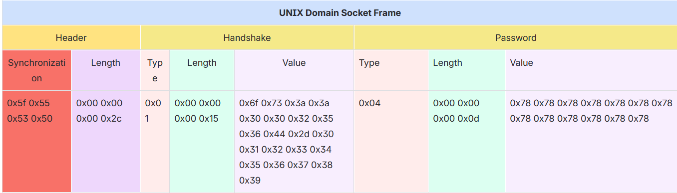
4.6.2.1 Handling Failures to Handshake
If for any reason the handshake process fails on one side of the UNIX domain socket or the other, then the side that fails the handshake process is responsible for sending a UNIX domain socket Frame containing an Error (using a Type 2 TLV field) that explains why the handshake process has failed .
R-UDS.21 - A USP Endpoint acting as a UNIX domain socket client or server MUST send a UNIX domain socket Frame containing a Type 2 (Error) TLV field if it can not process an incoming UNIX domain socket Frame that contains a Type 1 (Handshake) TLV field.
4.6.3 Sending USP Records across UNIX Domain Sockets
Once a UNIX domain socket is established between a server (either a USP Agent acting as a server or a USP Controller acting as a server) and a client (either a USP Agent acting as a client or a USP Controller acting as a client), and the USP Endpoints have successfully completed the handshake process, then either the USP Agent or USP Controller may begin sending UNIX domain socket Frames that contain a USP Record. A USP Endpoint sends a USP Record by sending a UNIX domain socket Frame with a Type 3 (USP Record) TLV field that contains the Google Protocol Buffer binary-encoded USP Record across the established UNIX domain socket connection.
R-UDS.22 - A USP Endpoint MUST send Google Protocol Buffer binary-encoded USP Records by utilizing a UNIX domain socket Frame that contains a Type 3 (USP Record) TLV field.
The following image shows an example of a UNIX domain socket Frame that contains a Type 3 (USP Record) TLV field, which is used for sending a USP Record between a USP Agent and USP Controller.
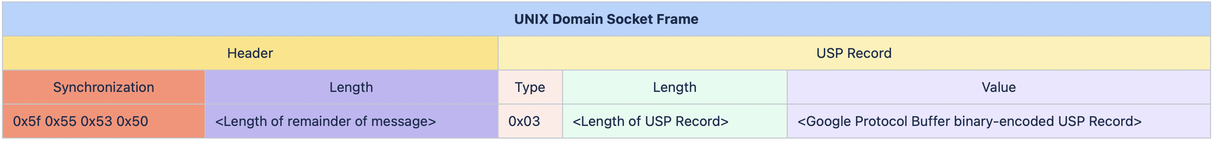
4.6.3.1 Handling Failures to Deliver USP Records
If a USP Endpoint acting as a UNIX domain socket client or server receives a UNIX domain socket Frame that contains a USP Record that cannot be extracted for processing (e.g., a UNIX domain socket Frame that includes a Type 3 TLV with text instead of a binary data, a malformed USP Record), a UNIX domain socket Frame containing a Type 2 (Error) TLV field is sent in response and the UNIX domain socket connection gets closed.
R-UDS.23 - A USP Endpoint acting as a UNIX domain socket client or server MUST send a UNIX domain socket Frame containing a Type 2 (Error) TLV field and terminate the UNIX Domain Socket connection, if it receives an incoming UNIX domain socket Frame containing a USP Record that cannot be extracted for processing.
Other USP Record processing failures (where the USP Record can be extracted, but other issues exist) are handled by R-MTP.5.
4.6.4 MTP Message Encryption
Encryption is not required for the UNIX domain socket MTP as all messages are exchanged between processes that reside internally within the device, but UNIX domain socket MTP message encryption can optionally be provided using certificates in TLS as described in section 10.5 and section 10.6 of RFC 6455 [23].
R-UDS.23a - USP Endpoints utilizing UNIX domain sockets for message transport, that choose to use TLS for MTP message encryption, MUST implement TLS 1.2 RFC 5246 [18] or later with backward compatibility to TLS 1.2.
R-UDS.23b - USP Controller certificates MAY contain domain names with wildcard characters per RFC 6125 [22] guidance.
4.6.5 Handling Other UNIX Domain Socket Failures
If a USP Endpoint acting as a UNIX domain socket client or server receives a TLV Message that cannot be parsed, a UNIX domain socket Frame containing a Type 2 (Error) TLV field is sent in response and the UNIX domain socket connection gets closed.
R-UDS.24 - A USP Endpoint acting as a UNIX domain socket client or server MUST send a UNIX domain socket Frame containing a Type 2 (Error) TLV field and terminate the UNIX Domain Socket connection, if it can not parse an incoming UNIX domain socket Frame.
4.6.6 Error Handling
If a USP Endpoint receives a UNIX domain socket Frame containing a Type 2 (Error) TLV field, then it closes the UNIX domain socket connection.
R-UDS.25 - A USP Endpoint acting as a UNIX domain socket client or server that receives a UNIX domain socket Frame containing a Type 2 (Error) TLV field MUST terminate the UNIX domain socket connection.
5 Message Encoding
USP requires a mechanism to serialize data to be sent over a Message Transfer Protocol. The description of each individual Message and the USP Record encoding scheme is covered in a section of this document and/or in the referenced specification. This version of the specification includes support for:
- Protocol Buffers Version 3 [4]
R-ENC.0 - An implementation using protocol buffers encoding to encode USP Messages (Requests, Responses, and Errors) MUST conform to the schema defined in usp-msg-1-5.proto.
R-ENC.1 - An implementation using protocol buffers encoding to encode USP Records MUST conform to the schema defined in usp-record-1-5.proto.
Protocol Buffers Version 3 uses a set of enumerated elements to coordinate encoding and decoding during transmission. It is intended that these remain backwards compatible, but new versions of the schema may contain new enumerated elements.
R-ENC.2 - If an Endpoint receives a USP payload containing an unknown enumeration value for a known field, the Endpoint MUST report the failure as described in R-MTP.5.
Protocol Buffers uses a datatype called oneof. This
means that the element contains elements of one or more varying
types.
R-ENC.3 - USP Records and USP
Messages that contain an element of type oneof MUST include
1 and only 1 instance of the element, which MUST contain one of the
possible elements.
R-ENC.4 - A USP Record that violates R-ENC.3 MUST be discarded.
R-ENC.5 - A USP Message that violates R-ENC.3 SHOULD return an error of type 7004 (Invalid Arguments).
5.1 Parameter and Argument Value Encoding
usp-msg-1-5.proto specifies that Parameter and argument values in USP Messages are represented as Protocol Buffers Version 3 strings (which are UTF-8-encoded).
This section specifies how Parameter and argument values are converted to and from Protocol Buffers Version 3 strings.
R-ENC.6 - Parameter and argument values MUST be converted to and from Protocol Buffers Version 3 strings using the string representations of the TR-106 Appendix I.4 [2] data types.
TR-106 Appendix I.4 states that “Parameters make use of a limited subset of the default SOAP data types”. The SOAP 1.1 specification [39] states that all SOAP simple types are defined by the XML Schema Part 2: Datatypes specification [40], and this is the ultimate reference.
In practice there should be few surprises, e.g., XML Schema Part 2, Section 3.3.22 [40] states that it has a lexical representation consisting of a finite-length sequence of decimal digits (#x30-#x39).
Some of the encoding rules are quite complicated, e.g. SOAP 1.1,
Section 5.2.3 [39] states that
base64 line length restrictions don’t apply to SOAP, and
XML Schema Part 2, Section 3.2.7 [40] has a lot of detail about which
aspects of ISO 8601 are and are not supported by the
dateTime data type.
6 End to End Message Exchange
USP Messages are exchanged between Controllers and Agents. In some deployment scenarios, the Controller and Agent have a direct connection. In other deployment scenarios, the messages exchanged by the Controller and Agent traverse multiple intermediate MTP Proxies. The latter deployment scenario typically occurs when the Agent or Controller is deployed outside the proximal or Local Area Network. In both types of scenarios, the End-to-End (E2E) message exchange capabilities of USP permit the:
- Exchange of USP Records within an E2E Session Context that allows
for:
- Integrity protection for non-payload fields
- Protected and unprotected payloads
- Segmentation and reassembly of E2E Messages that would be too large to transfer through the intermediate MTP Proxies.
- Exchange of USP Records without an E2E Session Context that allows
for:
- Integrity protection for non-payload fields
- Unprotected payloads or protected payloads where the payload protection security mechanism doesn’t require a concept of a session (e.g., COSE)
Protected payloads provide a secure message exchange (confidentiality, integrity and identity authentication) through exchange of USP Messages that are secured by the originating and receiving USP Endpoints.
USP makes use of USP Records to exchange USP Messages between Endpoints, see Record Definition for a description of the USP Record fields.
R-E2E.1 - A receiving USP
Endpoint MUST ignore any Record that does not contain its own Endpoint
Identifier as the to_id field of the Record.
R-E2E.2 – A USP Record with
record_type = session_context MUST contain at least one
payload field, or a non-zero retransmit_id.
(DEPRECATED)
Note: the R-E2E.2 requirement was deprecated in USP 1.2, because sending a Session Context Record without a payload is useful for restarting a Session Context
Note: the requirements below reference Objects and Parameters used to manage the E2E Session. These are specified in the Device:2 Data Model [3].
Note: The USP Record Encapsulation section was moved to USP Record Encapsulation in USP 1.2.
6.1 Exchange of USP Records within an E2E Session Context
When exchanging USP Records within an E2E Session Context,
record_type of session_context is used, and
all required parameters for record_type of
session_context are supplied.
When a USP Record that is received within an E2E Session Context contains a USP Message request, its associated response or error message is sent within an E2E Session Context, unless otherwise specified (see Requests, Responses and Errors).
6.1.1 Establishing an E2E Session Context
For the exchange of USP Records within an E2E Session Context to happen between two USP Endpoints, an E2E Session Context (Session Context) is established between the participating USP Endpoints. The Session Context is uniquely identified within the USP Endpoint by the combination of the Session Identifier and remote USP Endpoint’s Identifier.
In USP, either a Controller or an Agent can begin the process of
establishing a Session Context. This is done by the Controller or Agent
sending a USP Record with a session_id field that is not
currently associated with the Agent/Controller combination and a
sequence_id field value of 1. Note that a
Record with an empty payload can be used to establish a new Session
Context.
R-E2E.3 – Session Context identifiers MUST be generated by the USP Endpoint that originates the session such that it is greater than 1 and scoped to the remote USP Endpoint.
When a Session Context had been previously established between an
Agent and Controller and the remote USP Endpoint receives a USP Record
with a different session_id field, the remote USP Endpoint
will restart the Session Context using the new session_id
field.
R-E2E.4 – When a USP Endpoint
receives a USP Record from another USP Endpoint where there is no
established Session Context, and the USP Record includes a Session
Context identifier, and the USP Endpoint is configured to allow Session
Context to be used with the other Endpoint, the USP Endpoint MUST start
a new Session Context for the remote USP Endpoint, and initialize the
sequence_id field to 1.
R-E2E.5 – At most one (1) Session Context is established between an Agent and Controller.
R-E2E.6 – When a USP Endpoint
receives a USP Record from a remote USP Endpoint with a different
Session Context identifier than was previously established, the
receiving USP Endpoint MUST start a new Session Context for the remote
USP Endpoint, using the session_id from the received USP
Record, and initialize the sequence_id field to
1.
Note: Implementations need to consider if outstanding USP Messages that have not been transmitted to the remote USP Endpoint need to be transmitted within the newly established Session Context.
R-E2E.6a – When an Agent is configured not to allow Session Context or does not support Session Context and receives a USP Record initiating Session Context, the Agent MUST reply with a Disconnect Record and MUST include reason_code and reason fields indicating Session Context is not allowed (code 7106 from USP Record Errors).
When a Controller is configured to require Session Context and receives a Disconnect Record indicating Session Context is not allowed or supported by the Agent, the Controller is expected to terminate the MTP session.
R-E2E.6b – If an Agent needs to terminate a Session Context without terminating an existing MTP connection where Session Context is being used, it MUST send a Disconnect Record and MUST include reason_code and reason indicating Session Context is being terminated (code 7105 from USP Record Errors).
6.1.1.1 Session Context Expiration
Sessions Contexts have a lifetime and can expire. The expiration of
the Session Context is handled by the
Device.LocalAgent.Controller.{i}.E2ESession.SessionExpiration
Parameter in the Agent. If the Agent does not see activity (an exchange
of USP Records) within the Session Context, the Agent considers the
Session Context expired and for the next interaction with the Controller
a new Session Context is established.
R-E2E.7 – When a Session Context between a Controller or Agent expires the Agent MUST initiate a new Session Context upon the next interaction with the remote USP Endpoint or from a Session Context request by the remote USP Endpoint.
6.1.1.2 Exhaustion of Sequence Identifiers
USP Endpoints identify the USP Record using the
sequence_id field. When the sequence_id field
for a USP Record that is received or transmitted by a USP Endpoint nears
the maximum value that can be handled by the USP Endpoint, the USP
Endpoint will attempt to establish a new Session Context in order to
avoid a rollover of the sequence_id field.
R-E2E.8 – When a USP Endpoint
receives a USP Record with a value of the sequence_id field
that is within 10,000 of the maximum size for the data type of the
sequence_id field, the USP Endpoint MUST establish a new
Session Context with the remote USP Endpoint.
R-E2E.9 – When a USP Endpoint
transmits a USP Record with a value of the sequence_id
field that is within 10,000 of the maximum size for the data type of the
sequence_id field, the USP Endpoint MUST establish a new
Session Context with the remote USP Endpoint upon its next contact with
the remote USP Endpoint.
6.1.1.3 Failure Handling in the Session Context
In some situations, (e.g., TLS negotiation handshake) the failure to
handle a received USP Record is persistent, causing an infinite cycle of
“receive
failure/request->session/establish->session/receive->failure”
to occur. In these situations, the Agent enforces a policy as defined in
this section regarding establishment of failed Session Contexts or
failed interactions within a Session Context. The policy is controlled
by the Device.LocalAgent.Controller.{i}.E2ESession.Enable
Parameter.
R-E2E.10 – When retrying USP Records, the Agent MUST use the following retry algorithm to manage the retransmission Session Context establishment procedure:
The retry interval range is controlled by two Parameters, the minimum wait interval and the interval multiplier, each of which corresponds to a data model Parameter, and which are described in the table below. The factory default values of these Parameters MUST be the default values listed in the Default column. They MAY be changed by a Controller with the appropriate permissions at any time.
| Descriptive Name | Symbol | Default | Data Model Parameter Name |
|---|---|---|---|
| Minimum wait interval | m | 5 seconds | Device.LocalAgent.Controller.{i}.E2ESession.SessionRetryMinimumWaitInterval |
| Interval multiplier | k | 2000 | Device.LocalAgent.Controller.{i}.E2ESession.SessionRetryIntervalMultiplier |
| Retry Count | Default Wait Interval Range (min-max seconds) | Actual Wait Interval Range (min-max seconds) |
|---|---|---|
| #1 | 5-10 | m - m.(k/1000) |
| #2 | 10-20 | m.(k/1000) - m.(k/1000)^2 |
| #3 | 20-40 | m.(k/1000)^2 - m.(k/1000)^3 |
| #4 | 40-80 | m.(k/1000)^3 - m.(k/1000)^4 |
| #5 | 80-160 | m.(k/1000)^4 - m.(k/1000)^5 |
| #6 | 160-320 | m.(k/1000)^5 - m.(k/1000)^6 |
| #7 | 320-640 | m.(k/1000)^6 - m.(k/1000)^7 |
| #8 | 640-1280 | m.(k/1000)^7 - m.(k/1000)^8 |
| #9 | 1280-2560 | m.(k/1000)^8 - m.(k/1000)^9 |
| #10 and subsequent | 2560-5120 | m.(k/1000)^9 - m.(k/1000)^10 |
R-E2E.11 - Beginning with the tenth retry attempt, the Agent MUST choose from the fixed maximum range. The Agent will continue to retry a failed session establishment until a USP Message is successfully received by the Agent or until the SessionExpiration time is reached.
R-E2E.12 – Once a USP Record is successfully received, the Agent MUST reset the Session Context retry count to zero for the next Session Context establishment.
R-E2E.13 – If a reboot of the Agent occurs, the Agent MUST reset the Session Context retry count to zero for the next Session Context establishment.
6.1.2 USP Record Exchange
Once a Session Context is established, USP Records are created to
exchange payloads in the Session Context. USP Records are uniquely
identified by their originating USP Endpoint Identifier
(from_id), Session Context identifier
(session_id) and USP Record sequence identifier
(sequence_id).
6.1.2.1 USP Record Transmission
When an originating USP Endpoint transmits a USP Record, it creates
the USP Record with a monotonically increasing sequence identifier
(sequence_id).
R-E2E.14 – When an originating USP Endpoint transmits a USP Record, it MUST set the sequence identifier of the first transmitted USP Record in the Session Context to 1.
R-E2E.15 – When an originating USP Endpoint transmits additional USP Records, the originating USP Endpoint MUST monotonically increase the sequence identifier from the last transmitted USP Record in the Session Context by one (1).
To communicate the sequence identifier of the last USP Record
received by a receiving USP Endpoint to the originating USP Endpoint,
whenever a USP Endpoint transmits a USP Record the originating USP
Endpoint communicates the next sequence identifier of a USP Record it
expects to receive in the expected_id field. The receiving
USP Endpoint uses this information to maintain its buffer of outgoing
(transmitted) USP Records such that any USP Records with a sequence
identifier less than the expected_id can be removed from
the receiving USP Endpoints buffer of transmitted USP Records for this
Session Context.
R-E2E.16 – When an originating
USP Endpoint transmits a USP Record, the originating USP Endpoint MUST
preserve it in an outgoing buffer, for fulfilling retransmit requests,
until the originating USP Endpoint receives a USP Record from the
receiving USP Endpoint with a greater expected_id.
R-E2E.17 – When an originating USP Endpoint transmits a USP Record, the originating USP Endpoint MUST inform the receiving USP Endpoint of the next sequence identifier in the Session Context for a USP Record it expects to receive.
6.1.2.2 Payload Security within the Session Context
The value of the payload_security field defines the type
of payload security that is performed in the Session Context. Once a
Session Context is established the payload security stays the same
throughout the lifetime of the Session Context.
R-E2E.18 – The originating USP
Endpoint MUST use the same value in the payload_security
field for all USP Records within a Session Context.
6.1.2.3 USP Record Reception
USP Records received by a USP Endpoint have information that is used by the receiving USP Endpoint to process:
- The payload contained within the USP Record,
- A request to retransmit a USP Record, and
- The contents of the outgoing buffer to clear the USP Records that the originating USP Endpoint has indicated it has received from the receiving USP Endpoint.
As USP Records can be received out of order or not at all, the
receiving USP Endpoint only begins to process a USP Record when the
sequence_id field of the USP Record in the Session Context
is the sequence_id field that the receiving USP Endpoint
expects to receive. The following figure depicts the high-level
processing for USP Endpoints that receive a USP Record.
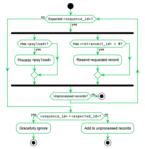
R-E2E.19 – The receiving USP
Endpoint MUST ensure that the value in the payload_security
field for all USP Records within a Session Context is the same and fail
the USP Record if the value of the payload_security field
is different.
R-E2E.20 – Incoming USP Records MUST be processed per the following rules:
- If the USP Record contains a
sequence_idfield larger than the nextexpected_idvalue, the USP Record is added to an incoming buffer of unprocessed USP Records. - If the
sequence_idis less that the nextexpected_id, the Endpoint MUST gracefully ignore the USP Record. - If the
sequence_idmatches theexpected_id, for the USP Record and any sequential USP Records in the incoming buffer:- If the payload is not empty, it is passed to the implementation for
processing based on the type of payload in the
payload_securityfield and if the payload requires reassembly according to the values of thepayload_sar_stateandpayloadrec_sar_statefields. - If a
retransmit_idfield is non-zero, the USP Record with the sequence identifier of theretransmit_idfield is resent from the outgoing buffer.
- If the payload is not empty, it is passed to the implementation for
processing based on the type of payload in the
- The
expected_idfield for new outgoing Records is set tosequence_idfield + 1 of this USP Record.
6.1.2.3.1 Failure Handling of Received USP Records Within a Session Context
When a receiving USP Endpoint fails to either buffer or successfully process a USP Record, the receiving USP Endpoint initiates a new Session Context.
R-E2E.21 – When a USP Endpoint that receives a USP Record within a Session Context that fails to buffer or successfully process (e.g., decode, decrypt, retransmit) the USP Endpoint MUST start a new Session Context.
6.1.2.4 USP Record Retransmission
An Agent or Controller can request to receive USP Records that it
deems as missing at any time within the Session Context. The originating
USP Endpoint requests a USP Record from the receiving USP Endpoint by
placing the sequence identifier of the requested USP Record in the
retransmit_id field of the USP Record to be
transmitted.
The receiving USP Endpoint will determine if USP Record exists and then re-send the USP Record to the originating USP Endpoint.
If the USP Record doesn’t exist, the USP Endpoint that received the USP Record will consider the USP Record as failed and perform the failure processing as defined in section Failure Handling of Received USP Records.
To guard against excessive requests to retransmit a specific USP
Record, the USP Endpoint checks to see if the number of times the USP
Record has been retransmitted is greater than or equal to maximum times
a USP Record can be retransmitted as defined in the
Device.LocalAgent.Controller.{i}.E2ESession.MaxRetransmitTries
Parameter. If this condition is met, then the USP Endpoint that received
the USP Record with the retransmit request will consider the USP Record
as failed and perform the failure processing as defined in section
Failure Handling of Received USP Records.
6.1.3 Guidelines for Handling Session Context Restarts
A Session Context can be restarted for a number of reasons (e.g., sequence id exhaustion, errors, manual request). When a Session Context is restarted, the USP Endpoints could have USP Records that have not been transmitted, received or processed. This section provides guidance for USP Endpoints when the Session Context is restarted.
The originating Endpoint is responsible for determining the policy for recovering from USP Records that were not transmitted. For example, the policy could be to resend the USP Message conveyed through the USP Record, or to simply discard the USP Message.
R-E2E.22 – The receiving USP
Endpoint MUST successfully process the USP Record through the
expected_id field that it last transmitted in the previous
session.
When a USP Endpoint receives a USP Record that cannot pass an
integrity check or that has an incorrect value in the
session_id field, the Session Context is restarted.
R-E2E.23 – USP Records that do not pass integrity checks MUST be silently ignored and the receiving USP Endpoint MUST restart the Session Context.
This allows keys to be distributed and enabled under the old session keys and then request a session restarted under the new keys.
R-E2E.24 – USP Records that pass
the integrity check but have an invalid value in the
session_id field MUST be silently ignored and the receiving
USP Endpoint MUST restart the Session Context.
6.1.4 Segmented Message Exchange
Since USP can use different types of MTPs, some MTPs place a constraint on the size of the USP Record that it can transport. To handle this, USP has a Segmentation and Reassembly function. When this Segmentation and Reassembly function is performed by Controller and Agent, it removes the possibly that the message may be blocked (and typically) dropped by the intermediate transport servers. A Segmentation and Reassembly example is shown in the figure below where the ACS Controller segments the USP Message within the USP Record of 64K bytes because the STOMP MTP Endpoint (in this example) can only handle frame body up to 64K bytes.
While the sequence_id field identifies the USP Record
sequence identifier within the context of a Session Context and the
retransmit_id field provides a means of a receiving USP
Endpoint to indicate to the transmitting USP Endpoint that it needs a
specific USP Record to ensure information fields are processed in a
first-in-first-out (FIFO) manner, the Segmentation and Reassembly
function allows multiple payloads to be segmented by the transmitting
USP Endpoint and reassembled by the receiving USP Endpoint by augmenting
the USP Record with additional information fields without changing the
current semantics of the USP Record’s field definitions. This is done
using the payload_sar_state and
payloadrec_sar_state fields in the USP Record to indicate
status of the segmentation and reassembly procedure. This status along
with the existing sequence_id, expected_id and
retransmit_id fields and the foreknowledge of the maximum
allowed USP Record size (configurable by the
Device.LocalAgent.Controller.{i}.E2ESession.MaxUSPRecordSize
parameter) provide the information needed for two USP Endpoints to
perform segmentation and reassembly of payloads conveyed by USP Records.
In doing so, the constraint imposed by MTP Endpoints (that could be
intermediate MTP Endpoints) that do not have segmentation and reassembly
capabilities are alleviated. USP Messages of any size can now be
conveyed across any USP MTP Endpoint as depicted below:
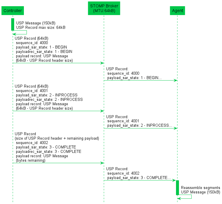
Note: the 64k size limit is not inherent to the STOMP protocol. It is merely provided here as an example.
Note: for other protocols (e.g., MQTT), the maximum allowed size
by the MTP may also include its own header size, not only the conveyed
payload (e.g., MQTT packet size). In this case, the
MaxUSPRecordSize value must be a smaller value than the
maximal size of the MTP.
6.1.4.1 SAR function algorithm
The following algorithm is used to provide the SAR function.
6.1.4.1.1 Originating USP Endpoint
For each USP Message segment the Payload:
- Compose the USP Message.
- If
payload_securityisTLS12, encrypt the USP Message. TLS will segment the encrypted Message per the maximum allowed TLS record size.- If all TLS records + Record header fields are less than the maximum allowed USP Record size, then a single USP Record is sent.
- Otherwise, segmentation of the USP Record will need to be done.
- If the record size of a single TLS record + USP Record header fields is less than the maximum allowed USP Record size, exactly one TLS record can be included in a USP Record.
- If the TLS record size + Record header fields is greater than the maximum allowed USP Record size, the TLS record is segmented across multiple USP Records.
- If the Message is transmitted using
PLAINTEXTand the Message + Record header fields are greater than the maximum allowed USP Record size, the USP Record is segmented. - Set the
payload_sar_statefield for each transmitted Record.- If there is only one Record,
payload_sar_state=NONE (0). - If there is more than one USP Record, the
payload_sar_statefield is set toBEGIN (1)on the first Record,COMPLETE (3)on the last Record, andINPROCESS (2)on all Records between the two.
- If there is only one Record,
- Set the
payloadrec_sar_statefield for each transmitted Record.- If there is only one Record or one Secure Message Exchange TLS
record per USP Record,
payloadrec_sar_state=NONE (0). - If Secure Message Exchange TLS records or a
PLAINTEXTpayload are segmented across multiple USP Records,payloadrec_sar_state=BEGIN (1)on a Record that contains the initial segment of a TLS record orPLAINTEXTpayload,COMPLETE (3)on a Record that contains the final segment of a TLS record orPLAINTEXTpayload, andINPROCESS (2)on all Records containing segments between initial and final segments of a TLS record orPLAINTEXTpayload.
- If there is only one Record or one Secure Message Exchange TLS
record per USP Record,
- Each Record is sent (within a Session Context) using the procedures defined in the USP Record Message Exchange section above.
The effect of the above rules for PLAINTEXT payloads or
for Secure Message Exchange with a single TLS record is that
payloadrec_sar_state will be the same as
payload_sar_state for all Records used to communicate the
USP Message.
Note: The maximum allowed USP Record size can be exposed via the
data model using the
Device.LocalAgent.Controller.{i}.E2ESession.MaxUSPRecordSize
Parameter.
6.1.4.1.2 Receiving Endpoint
For each USP Message reassemble the segmented payload:
- When a USP Record that indicates segmentation has started, store the
USP Records until a USP Record is indicated to be complete. A completed
segmentation is where the USP Record’s
payload_sar_stateandpayloadrec_sar_statehave a value ofCOMPLETE (3). - Follow the procedures in USP Record Retransmission to retransmit any USP Records that were not received.
- Once the USP Record is received that indicates that the segmentation
is complete, reassemble the payload by appending the payloads using the
monotonically increasing
sequence_idfield’s value from the smaller number to larger sequence numbers. The reassembly keeps the integrity of the instances of the payload field’s payload records. To keep the integrity of the payload record, the payload record is reassembled using thepayloadrec_sar_statevalues. - Reassembly of the payload that represents the USP Message is complete.
If the segmentation and reassembly fails for any reason, the USP Endpoint that received the segmented USP Records will consider the last received USP Record as failed and perform the failure processing as defined in section Failure Handling of Received USP Records.
6.1.4.2 Segmentation Examples
The following examples show the values assigned to
payload_sar_state and payloadrec_sar_state
fields for various permutations of payload_security, and
maximum USP Record size and Secure Message Exchange maximum TLS record
size relative to the size of the USP Message. The examples are not
exhaustive.
Case 1: payload_security = PLAINTEXT, single USP Record
Conditions:
- Maximum USP Record size > size of (USP Message + USP Record header)
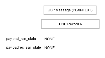
Case 2: payload_security = PLAINTEXT, fragmented across multiple USP Records
Conditions:
- Maximum USP Record size < size of (USP Message + USP Record header)
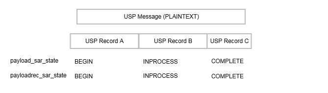
Case 3: payload_security = TLS12, single TLS record, single USP Record
Conditions:
- Maximum TLS record size > size of (USP Message + TLS record header)
- Maximum USP Record size > size of USP Message + size of TLS record header + size of USP Record header
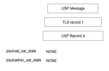
Case 4: Payload_security = TLS12, all TLS records in a single USP Record
Conditions:
- Maximum TLS record size < size of (USP Message + TLS record header)
- Maximum USP Record size > size of all TLS records + size of USP Record header
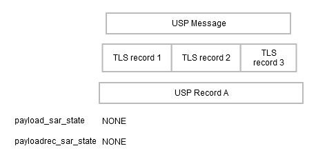
Case 5: Payload_security = TLS12, single TLS record fragmented across multiple USP Records
Conditions:
- Maximum TLS record size > size of (USP Message + TLS record header)
- Maximum USP Record size < size of (TLS record + USP Record header)
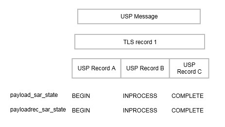
Case 6: Payload_security = TLS12, multiple TLS records, one TLS record per USP Record
Conditions:
- Maximum TLS record size < size of (USP Message + TLS record header)
- Maximum USP Record size > maximum TLS record size + size of USP Record header
- Maximum USP Record size < size of USP Message + size of TLS record header + size of USP Record header
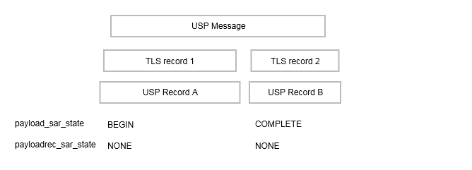
Case 7: Payload_security = TLS12, multiple TLS records, some TLS records fragmented across multiple USP Records
Conditions:
- Maximum TLS record size < size of (USP Message + TLS record header)
- Maximum USP Record size < size of (some TLS records + USP Record header)
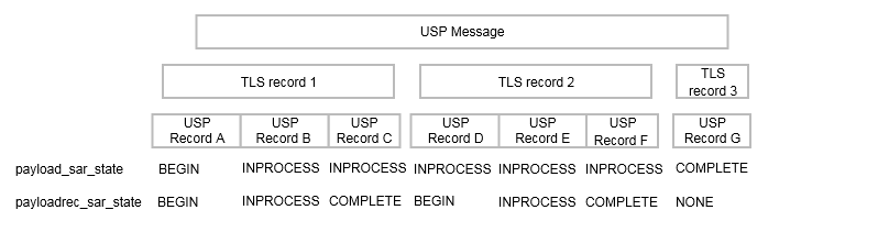
6.1.5 Handling Duplicate USP Records
Circumstances may arise (such as multiple Message Transfer Protocols,
retransmission requests) that cause duplicate USP Records (those with an
identical sequence_id and session_id fields
from the same USP Endpoint) to arrive at the target USP Endpoint.
R-E2E.25 - When exchanging USP
Records with an E2E Session Context, if a target USP Endpoint receives a
USP Record with duplicate sequence_id and
session_id fields from the same originating USP Endpoint,
it MUST gracefully ignore the duplicate USP Record.
6.2 Exchange of USP Records without an E2E Session Context
When the exchange of USP Records without an E2E Session Context is
used, the record_type is set to
no_session_context.
When a USP Record that is received without an E2E Session Context contains a USP Message request, its associated response or error message is sent without an E2E Session Context, unless otherwise specified (see Requests, Responses and Errors).
R-E2E.26 - A
record_type of no_session_context MUST be used
for exchange of USP Records without an E2E Session Context. A non-zero
payload MUST be included.
6.2.1 Failure Handling of Received USP Records Without a Session Context
When a receiving USP Endpoint fails to either buffer or successfully process a USP Record, the receiving USP Endpoint reports a failure.
R-E2E.27 (DEPRECATED) - When a
USP Endpoint that receives a USP Record without a Session Context that
fails to buffer or successfully process (e.g., decode, decrypt,
retransmit) the USP Endpoint SHOULD send a DisconnectRecord
(as described in R-MTP.7 for
Agents).
Note: Requirement R-E2E.27 was removed in USP 1.3, replaced by the behavior defined in R-MTP.5
Note that R-MTP.7 says
Agents should send a DisconnectRecord when terminating an
MTP. Controllers can also send a DisconnectRecord in this
case. The MTP can stay connected. Brokered MTP sessions are expected to
remain but other MTP connections could be closed.
6.3 Validating the Integrity of the USP Record
When a USP Record is transmitted to a USP Endpoint, the transmitting
USP Endpoint has the capability to protect the integrity of the
non-payload fields of the USP Record. The payload field is
not part of the generation or verification process, as the expectation
is that this element will be secured using an E2E security protection
mechanism (payload_security other than PLAINTEXT).
The integrity of the USP Record is required to be validated when the USP Record cannot be protected by the underlying MTP.
R-E2E.28 - When a USP Record is received or transmitted the following conditions MUST apply for the USP Record to be considered protected by the underlying MTP:
- The MTP is encrypted per requirements in the applicable MTP section
- The peer MTP certificate contains an Endpoint ID and this Endpoint
ID is the same as the USP Record
from_idfield OR the peer MTP certificate is directly associated (e.g., referenced from aDevice.LocalAgent.Controller.{i}.CredentialParameter) with a Controller whose Endpoint ID matches the USP Recordfrom_idfield. - The peer MTP certificate is that of a Trusted Broker.
R-E2E.29 – Unless protected by the underlying MTP, when a USP Endpoint transmits a USP Record, the USP Endpoint MUST protect the integrity of the non-payload portion of the USP Record.
R-E2E.30 – When a USP Endpoint receives a USP Record, the USP Endpoint MUST verify the integrity of the non-payload portion of the USP Record when the USP Record contains the mac_signature field or the USP Endpoint is not protected by the underlying MTP.
The integrity of the non-payload fields is accomplished by the
transmitting USP Endpoint generating a Message Authentication Code (MAC)
or signature of the non-payload fields which is then placed into the
mac_signature field where the receiving USP Endpoint then verifies the
MAC or signature as appropriate. The method to generate and validate MAC
or signature depends on the value of the payload_security
field. If the value of the payload_security field is
PLAINTEXT then the integrity validation method always uses
the signature method described in section Using the Signature Method to
Validate the Integrity of USP Records. If the value of the
payload_security field is TLS12 then the
validation method that is used is dependent on whether the TLS handshake
has been completed. If the TLS handshake has not been completed, the
signature method described in section Using the Signature Method to
Validate the Integrity of USP Records is used otherwise the MAC method
described in section Using TLS to Validate the Integrity of USP Records
is used.
6.3.1 Using the Signature Method to Validate the Integrity of USP Records
When the transmitting USP Endpoint protects the integrity of the
non-payload fields of the USP Record using the signature method in this
section, the non-payload fields are protected by signing a hash of the
non-payload fields using the private key of the sending USP Endpoint’s
certificate. The receiving USP Endpoint then verifies the integrity
using either the public key of the certificate in the USP Record
sender_cert field or of the certificate used for Secure
Message Exchange.
This signature method uses the SHA-256 hash algorithm, as defined in
FIPS PUB 180-4 Secure Hash Standard (SHS) [35], and the NIST P-256 curve that
generates a signature for the hash using the Digital Signature Standard
(DSS) scheme as defined in FIPS PUB 186-4 Digital Signature Standard
(DSS) [36]. To reduce
the burden of requiring a strong source of randomness, the signature
algorithm may apply the method described in RFC 6979 [27] to deterministically derive
encryption parameters. The signature must be ASN.1 DER-encoded as
described in RFC 3279 [12], we will refer
to this signature scheme as ECDSA_P256_SHA256_ASN1 in this
specification.
R-E2E.31 – When using the
signature method to protect the integrity of the non-payload portion of
the USP Record, the transmitting USP Endpoint MUST protect the integrity
using the ECDSA_P256_SHA256_ASN1 signature scheme, as
defined in this specification, to sign and verify the protection. The
transmitting USP Endpoint MUST create the signature using the private
key of the transmitting USP Endpoint’s certificate. The receiving USP
Endpoint MUST verify the signature using the public key of the
transmitted sender’s certificate.
6.3.2 Using TLS to Validate the Integrity of USP Records
When the transmitting and receiving USP Endpoints have established a
TLS session, the transmitting USP Endpoint no longer needs to generate a
signature or transmit the sender’s certificate with the USP Record.
Instead, the transmitting USP Endpoint generates a MAC that is verified
by the receiving USP Endpoint. The MAC ensures the integrity of the
non-payload fields of the USP Record. The MAC mechanism used in USP for
this purpose is the SHA-256 keyed-Hash Message Authentication Code
(HMAC) algorithm. The keys used for the HMAC algorithm are derived in
accordance with RFC 5705 [20] when using TLS
1.2 or in accordance with the updated version found in RFC 8446 [33] when using TLS 1.3. These
procedures require the following inputs: a label, a context and the
length of the output keying material. The label used must be
“EXPORTER-BBF-USP-Record”, the context must be empty (note
that, for TLS 1.2, an empty context, i.e. zero length, is different from
no context at all) and the output length must be 64 octets, where the
first 32 octets will be used as the client key and the other 32 octets
as the server key (in TLS terms). When using TLS 1.2, the PRF used must
be the one defined in RFC 5246 [18] with SHA-256 Hash.
R-E2E.32 – When generating or
validating the MAC or signature to protect the integrity of the USP
Record, the sequence of the non-payload fields MUST use the field
identifier of the USP Record’s protobuf specification proceeding from
lowest to highest. The non-payload fields in the Record definition
(other than the mac_signature field itself) MUST be used
first and then the fields of the SessionContextRecord if
applicable.
R-E2E.32.1 – When generating or validating the MAC or signature, all non-payload fields MUST be appended as byte arrays and fed into the MAC or signature generation function with the following conditions:
- uint64 types MUST be passed as 8 bytes in big endian ordering
- uint32 types MUST be passed as 4 bytes in big endian ordering
- enum types MUST be treated as uint32
- string types MUST be passed as UTF-8 encoded byte array
- bytes types MUST be passed as is
R-E2E.33 – If using the TLS MAC method to protect the integrity of a USP Record, and a USP Endpoint receives a USP Record, the USP Endpoint MUST verify the MAC using the SHA-256 HMAC algorithm for the non-payload portion of the USP Record.
R-E2E.34 – If using the TLS MAC method to protect the integrity of a USP Record, when generating or validating the MAC of the USP Record, the sequence of the non-payload fields MUST use the field identifier of the USP Record’s protobuf specification proceeding from lowest to highest.
R-E2E.35 – If using the TLS MAC method to protect the integrity of a USP Record, when generating or validating the MAC of the USP Record, the USP Endpoint MUST derive the keys in accordance with RFC 5705 [20] when using TLS 1.2 or with accordance with RFC 8446 [33] when using TLS 1.3.
R-E2E.36 – If using the TLS MAC
method to protect the integrity of a USP Record, when generating or
validating the MAC of the USP Record, the USP Endpoint MUST use a label
value of “EXPORTER-BBF-USP-Record” and a zero length
context.
R-E2E.37 – If using the TLS MAC method to protect the integrity of a USP Record, when generating or validating the MAC of the USP Record, the USP Endpoint MUST generate 64 octets of keying material.
R-E2E.38 – If using the TLS MAC method to protect the integrity of a USP Record, when generating or validating the MAC of the USP Record, the USP Endpoint MUST use the TLS PRF defined in RFC 5246 [18] with SHA-256 Hash when using TLS 1.2 for End-to-End security.
R-E2E.39 – If using the TLS MAC method to protect the integrity of a USP Record, when generating the MAC of the USP Record, the USP Endpoint MUST use the first 32 octets of the keying material as the client key and the other 32 octets as the server key.
6.4 Secure Message Exchange
While message transport bindings implement point-to-point security,
the existence of broker-based message transports and transport proxies
creates a need for end-to-end security within the USP protocol.
End-to-end security is established by securing the payloads prior to
segmentation and transmission by the originating USP Endpoint and the
decryption of reassembled payloads by the receiving USP Endpoint. The
indication whether and how the USP Message has been secured is via the
payload_security field. This field defines the security
protocol or mechanism applied to the USP payload, if any. This section
describes the payload security protocols supported by USP.
6.4.1 TLS Payload Encapsulation
USP employs TLS as one security mechanism for protection of USP payloads in Agent-Controller message exchanges.
While traditionally deployed over reliable streams, TLS is a record-based protocol that can be carried over datagrams, with considerations taken for reliable and in-order delivery. To aid interoperability, USP Endpoints are initially limited to a single cipher specification, though future revisions of the protocol may choose to expand cipher support.
R-E2E.40 – When using TLS to
protect USP payloads in USP Records, USP Endpoints MUST implement TLS
1.2 or later (with backward compatibility to TLS 1.2) with the
ECDHE-ECDSA-AES128-GCM-SHA256 cipher for TLS 1.2 and the
TLS-AES128-GCM-SHA256 cipher for TLS 1.3.
R-E2E.40a - When using TLS to
protect USP payloads in USP Records, USP Endpoints MUST use ECDHE for
key exchange and MUST support the named group secp256r1
(NIST P-256 curve) for use in ECDHE.
R-E2E.40b - When using TLS to protect USP payloads in USP Records, USP Endpoints MUST use the ECDSA signature scheme with the NIST P-256 curve and SHA-256.
Note: The requirements listed above require a USP Endpoint to use X.509 certificates with an Elliptic-curve public key compatible with the NIST P-256 curve.
6.4.1.1 Session Handshake
When TLS is used as a payload protection mechanism for USP Message, TLS requires the use of the Session Context to negotiate its TLS session. The USP Endpoint that initiated the Session Context will act in the TLS client role when establishing the security layer. The security layer is constructed using a standard TLS handshake, encapsulated within one or more of the above-defined USP Record payload datagrams. Per the TLS protocol, establishment of a new TLS session requires two round-trips.
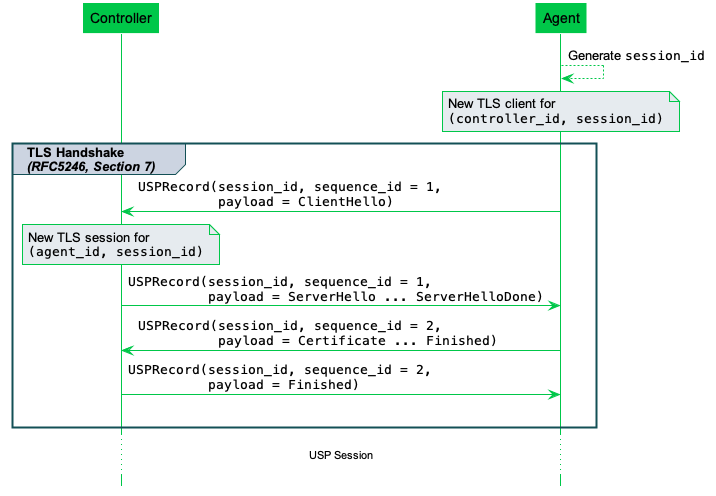
R-E2E.41 – USP Endpoints that
specify TLS12 in the payload_security field
MUST exchange USP Records within an E2E Session Context.
If the TLS session cannot be established for any reason, the USP Endpoint that received the USP Record will consider the USP Record as failed and perform the failure processing as defined in section Failure Handling of Received USP Records.
TLS provides a mechanism to renegotiate the keys of a TLS session without tearing down the existing session called TLS renegotiation. However, for E2E Message exchange in USP, TLS renegotiation is forbidden.
R-E2E.42 – USP Endpoints MUST NOT
accept requests for TLS renegotiation when used for E2E Message
exchange. USP Endpoints MAY send a TLS no_renegotiation
alert in response to a request for renegotiation.
6.4.1.2 Authentication
USP relies upon peer authentication using X.509 certificates, as provided by TLS. Each USP Endpoint identifier is identified within an X.509 certificate. The rules for authentication are provided in Authentication and Authorization.
R-E2E.43 – USP Endpoints MUST be mutually authenticated using X.509 certificates.
Agents will authenticate Controllers according to rules for analysis of Controller certificates requirements in Analysis of Controller Certificates. Controllers will authenticate Agents using the USP Endpoint identifier encoded in the Agent’s certificate as per Agent Authentication
7 Messages
USP contains messages to create, read, update, and delete Objects, perform Object-defined operations, and allow Agents to notify controllers of events. This is often referred to as CRUD with the addition of O (operate) and N (notify), or CRUD-ON.
Note: This version of the specification defines its Messages in Protocol Buffers v3. This part of the specification may change to a more generic description (normative and non-normative) if further encodings are specified in future versions.
These sections describe the types of USP Messages and the normative requirements for their flow and operation. USP Messages are described in a protocol buffers schema, and the normative requirements for the individual fields of the schema are outlined below.
7.1 Encapsulation in a USP Record
All USP Messages are encapsulated by a USP Record. The definition of the USP Record portion of a USP Message can be found in Record Definition, and the rules for managing transactional integrity are described in End to End Message Exchange.
7.2 Requests, Responses and Errors
The three types of USP Messages are Request, Response, and Error.
A request is a Message sent from a source USP Endpoint to a target USP Endpoint that includes fields to be processed and returns a response or error. Unless otherwise specified, all requests have an associated response. Though the majority of requests are made from a Controller to an Agent, the Notify and Register Messages follow the same format as a request but is sent from an Agent to a Controller.
R-MSG.0 - The target USP Endpoint MUST respond to a request Message from the source USP Endpoint with either a response Message or Error Message, unless otherwise specified (see The Operate Message and The Notify Message).
R-MSG.0a - The associated
response or error Message MUST be sent through the same type of USP
Record (i.e. A record_type of session_context or no_session_context) used along the
associated request Message.
R-MSG.1 - The target USP Endpoint MUST ignore or send an Error Message in response to Messages it does not understand.
Note: Requirement R-MSG.2 was removed in USP 1.2, because it did not align with the concept of brokered MTPs and long-lived connections in general.
R-MSG.3 - In any USP Message originating from an Agent, unless otherwise specified, Path Names reported from the Agent’s Instantiated Data Model MUST use Instance Number Addressing.
7.2.1 Handling Duplicate Messages
Circumstances may arise (such as multiple Message Transfer Protocols) that cause duplicate Messages (those with an identical Message ID) to arrive at the target USP Endpoint.
R-MSG.4 - If a target USP Endpoint receives a Message with a duplicate Message ID before it has processed and sent a Response or Error to the original Message, it MUST gracefully ignore the duplicate Message.
For Messages that require no response, it is up to the target Endpoint implementation when to allow the same Message ID to be re-used by the same source USP Endpoint.
7.2.2 Handling Search Expressions
Many USP Messages allow for search expressions to be used in the request. To help make Controller requests more flexible, it is desired that requests using search expressions that match zero Objects should receive a successful response. In these cases, the Agent is in the desired state the Controller intends, and the result should not interrupt the Controller’s application.
In the Messages below, this requirement is sometimes explicit, but it is stated here as a general requirement.
R-MSG.4a - Unless otherwise
specified, if a Request contains a Search Path, the associated Response
MUST result in a successful operation with an empty element
(i.e. oper_success{}) if the Search Path matches zero
Objects in the Agent’s Instantiated Data Model.
7.2.3 Example Message Flows
Successful request/response: In this successful Message sequence, a Controller sends an Agent a request. The Message header and body are parsed, the Message is understood, and the Agent sends a response with the relevant information in the body.
Note: this is not meant to imply that all request/response operations will be synchronous. Controllers can and should expect that Responses may be received in a different order than that in which Requests were made.
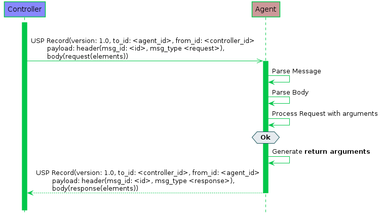
Failed request/response: In this failed Message sequence, a Controller sends an Agent a request. The Message header and body are parsed, but the Agent throws an error. The error arguments are generated and sent in an Error Message.
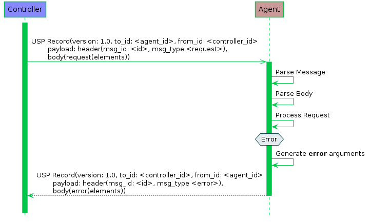
7.3 Message Structure
A Message consists of a header and body. When using Protocol Buffers [4], the fields of the header and body for different Messages are defined in a schema and sent in an encoded format from one USP Endpoint to another.
R-MSG.5 - A Message MUST conform to the schemas defined in usp-msg-1-5.proto.
See the section on USP Record Encapsulation for information about Protocol Buffers default behavior and required fields.
Every USP Message contains a header and a body. The header contains basic destination and coordination information, and is separated to allow security and discovery mechanisms to operate. The body contains the message itself and its arguments.
Each of the Message types and fields below are described with the field type according to Protocol Buffers [4], followed by its name.
7.3.1 The USP Message
Header header
R-MSG.6 - A Message MUST contain exactly one header field.
Body body
The Message Body that must be present in every Message. The Body field contains either a Request, Response, or Error field.
R-MSG.7 - A Message MUST contain exactly one body field.
7.3.2 Message Header
The Message Header includes a Message ID to associate Requests with Responses or Errors, and a field indicating the type of Message.
The purpose of the Message Header is to provide basic information necessary for the target Endpoint to process the message.
7.3.2.1 Message Header Fields
string msg_id
A locally unique opaque identifier assigned by the Endpoint that generated this Message.
R-MSG.8 - The msg_id field MUST be present in every Header.
R-MSG.9 - The msg_id field in the Message Header for a Response or Error that is associated with a Request MUST contain the Message ID of the associated request. If the msg_id field in the Response or Error does not contain the Message ID of the associated Request, the response or error MUST be ignored.
enum MsgType msg_type
This field contains an enumeration indicating the type of message contained in the Message body. It is an enumeration of:
    ERROR (0)
    GET (1)
    GET_RESP (2)
    NOTIFY (3)
    SET (4)
    SET_RESP (5)
    OPERATE (6)
    OPERATE_RESP (7)
    ADD (8)
    ADD_RESP (9)
    DELETE (10)
    DELETE_RESP (11)
    GET_SUPPORTED_DM (12)
    GET_SUPPORTED_DM_RESP (13)
    GET_INSTANCES (14)
    GET_INSTANCES_RESP (15)
    NOTIFY_RESP (16)
    GET_SUPPORTED_PROTO (17)
    GET_SUPPORTED_PROTO_RESP (18)
    REGISTER (19)
    REGISTER_RESP (20)
    DEREGISTER (21)
    DEREGISTER_RESP (22)
R-MSG.10 - The
msg_type field MUST be present in every Header. Though
required, it is meant for information only. In the event this field
differs from the req_type or resp_type in the
Message body (respectively), the type given in either of those elements
SHOULD be regarded as correct.
7.3.3 Message Body
The Message body contains the intended message and the appropriate fields for the Message type.
Every Message body contains exactly one message and its fields. When an Agent is the target Endpoint, these messages can be used to create, read, update, and delete Objects, or execute Object-defined operations. When a Controller is the target Endpoint, the Message will contain a notification, response, or an error.
7.3.3.1 Message Body Fields
oneof msg_body
This field contains one of the types given below:
Request request
This field indicates that the Message contains a request of a type given in the Request Message.
Response response
This field indicates that the Message contains a response of a type given in the Response Message.
Error error
This field indicates that the Message contains an Error Message.
7.3.3.2 Request Fields
oneof req_type
This field contains one of the types given below. Each indicates that the Message contains a Message of the given type.
    Get get
    GetSupportedDM get_supported_dm
    GetInstances get_instances
    Set set
    Add add
    Delete delete
    Operate operate
    Notify notify
    GetSupportedProtocol get_supported_protocol
    Register register
    Deregister deregister
7.3.3.3 Response Fields
oneof resp_type
This field contains one of the types given below. Each indicates that the Message contains a Message of the given type.
    GetResp get_resp
    GetSupportedDMResp get_supported_dm_resp
    GetInstancesResp get_instances_resp
    SetResp set_resp
    AddResp add_resp
    DeleteResp delete_resp
    OperateResp operate_resp
    NotifyResp notify_resp
    GetSupportedProtocolResp get_supported_protocol_resp
    RegisterResp register_resp
    DeregisterResp deregister_resp
7.3.3.4 Error Fields
fixed32 err_code
This field contains a numeric code (see Error Codes) indicating the type of error that caused the overall Message to fail.
string err_msg
This field contains additional information about the reason behind the error.
repeated ParamError param_errs
This field is present in an Error Message in response to an Add, Set,
or Delete Message when the allow_partial field is false and
detailed error information is available for each Object or Parameter
that have caused the Message to report an Error.
7.3.3.4.1 ParamError Fields
string param_path
This field contains a Path Name to the Object or Parameter that caused the error.
fixed32 err_code
This field contains a numeric code (see Error Codes) indicating the type of error that caused the Message to fail.
string err_msg
This field contains additional information about the reason behind the error.
7.4 Creating, Updating, and Deleting Objects
The Add, Set, and Delete requests are used to create, configure and remove Objects that comprise Service fields.
7.4.1 Selecting Objects and Parameters
Each Add, Set, and Delete request operates on one or more Path Names. For the Add request, these Path Names are references to Multi-Instance Objects. For all other requests, these Path Names can contain either addressing based identifiers that match zero or one Object or search based identifiers that match one or more Objects.
For Add and Set requests, each Object address or search is conveyed in a field that also contains a sub-field listing the Parameters to update in the matched Objects.
The Add response contains details about the success or failure of the creation of the Object and the Parameters set during its creation. In addition, it also returns those Parameters that were set by the Agent upon creation of the Object.
Note: The order of the data on the wire is not guaranteed to be in
the order an implementation may require to process a
Message piece by piece. Some common scenarios which an
Agent will need to handle:
- In Objects containing a union Object, the union member Object will only exist after the discriminator Parameter was set to the associated value
- Key Parameters need only to have unique values after the whole Message has been processed
- All explicit and hidden data dependencies need to be accounted for, so if related Parameters are changed, the order in which they occur in the Message do not make any difference to the outcome
For example, a Controller wants to create a new Wi-Fi network on an Agent. It could use an Add Message with the following fields:
    add {
      allow_partial: false
      create_objs {
        obj_path: "Device.WiFi.SSID."
        param_settings {
          param: "LowerLayers"
          value: "Device.WiFi.Radio.1."
          required: true
        }
        param_settings {
          param: "SSID"
          value: "NewSSIDName"
          required: true
        }
      }
    }
The Agent’s response would include the Object created (with its instance identifier) and the Unique Key Parameters of the created Object as defined in the Device:2 Data Model [3]:
    add_resp {
      created_obj_results {
        requested_path: "Device.WiFi.SSID."
        oper_status {
          oper_success {
            instantiated_path: "Device.WiFi.SSID.4."
            unique_keys {
              key: "BSSID"
              value: "112233445566"
            }
            unique_keys {
              key: "Name"
              value: "GuestNetwork1"
            }
            unique_keys {
              key: "Alias"
              value: "cpe-alias-1"
            }
          }
        }
      }
    }
7.4.2 Unique Key Immutability
In order to maintain addressing integrity of Multi-Instance Objects, the following prescriptions are made on the use of Unique Keys.
R-KEY.1 - Non-functional Unique Keys (as defined in TR-106 [2]) MUST NOT change in the Agent’s Instantiated Data Model after creation, as defined in R-ADD.5.
R-KEY.2 - Functional Unique Keys (as defined in TR-106 [2]) MAY change incidentally as part of normal operation, but any change MUST abide by the uniqueness rules (i.e., no conflict with other instances).
7.4.3 writeOnceReadOnly Parameter Access
There are several parameter access types defined in [2] that specify what a Controller is
allowed to do with a particular Parameter as defined in [3]. Of these,
writeOnceReadOnly affects the response of an Agent in
specific ways. A writeOnceReadOnly Parameter can be set
only once by a Controller, and then becomes read-only. In some cases,
the value is assigned by the Agent upon Object creation if not specified
by the Controller. The expected behavior is otherwise as follows:
- When a
writeOnceReadyOnlyParameter is set upon Object creation via theAddMessage, the Controller making the Add Request is considered to have set the Parameter. - When a
writeOnceReadOnlyParameter is updated via aSetMessage, an Agent will reject the update if the Parameter has already been set. writeOnceReadyOnlyParameters are reported asPARAM_READ_WRITE (1)in aGetSupportedDMResponse. Controllers should rely on knowledge of the Agent’s data model through other means (i.e., officially published data models) to determine that a parameter iswriteOnceReadOnly.
7.4.4 Using Allow Partial and Required Parameters
The Add, Set, and Delete requests contain a field called
“allow_partial”. This field determines whether the Message
should be treated as one complete configuration change, or a set of
individual changes, with regard to the success or failure of that
configuration.
For Delete, this is straightforward - if allow_partial
is true, the Agent returns a Response Message with
affected_paths and unaffected_path_errs
containing the successfully deleted Objects and unsuccessfully deleted
Objects, respectively. If allow_partial is
false, the Agent will return an Error Message if any
Objects fail to be deleted.
For the Add and Set Messages, Parameter updates contain a field
called “required”. This details whether the update or
creation of the Object should fail if a required Parameter fails.
This creates a hierarchy of error conditions for the Add and Set requests, such as:
Parameter Error -> Object Error -> Message Error
If allow_partial is true, but one or more required
Parameters fail to be updated or configured, the creation or update of a
requested Path Name fails. This results in an oper_failure
in the oper_status field and
updated_obj_result or created_obj_result
returned in the Add or Set response.
If allow_partial is false, the failure of any required
Parameters will cause the update or creation of the Object to fail,
which will cause the entire Message to fail. In this case, the Agent
returns an Error Message rather than a response Message.
Note: It is up to the individual implementation whether to abort and return an Error Message after the first error, or provide information about multiple failures.
If the Message was at least partially successful, the response will
make use of the oper_success field to indicate the
successfully affected Objects.
The oper_failure and oper_success fields as
well as Error Messages contain a field called param_errs,
which contains fields of type ParameterError or
ParamError. This is so that the Controller will receive the
details of failed Parameter updates regardless of whether the Agent
returned a Response or Error Message.
The logic can be described as follows:
allow_partial |
Required Parameters | Required Parameter Failed | Other Parameter Failed | Response/Error | Oper_status of Object | Contains param_errs |
|---|---|---|---|---|---|---|
true/false |
No | - | No | Response | oper_success |
No |
true/false |
No | - | Yes | Response | oper_success |
Yes |
true/false |
Yes | No | No | Response | oper_success |
No |
true/false |
Yes | No | Yes | Response | oper_success |
Yes |
true |
Yes | Yes | - | Response | oper_failure |
Yes |
false |
Yes | Yes | - | Error | N/A | Yes |
7.4.5 The Add Message
The Add Message is used to create new Instances of Multi-Instance Objects in the Agent’s Instantiated Data Model.
7.4.5.1 Add Example
In this example, the Controller requests that the Agent create a new
instance in the Device.LocalAgent.Controller table.
header {
  msg_id: "52867"
  msg_type: ADD
}
body {
  request {
    add {
      allow_partial: true
      create_objs {
        obj_path: "Device.LocalAgent.Controller."
        param_settings {
          param: "Enable"
          value: "true"
          required: false
        }
        param_settings {
          param: "EndpointID"
          value: "controller-temp"
          required: false
        }
      }
    }
  }
}
header {
msg_id: "52867"
msg_type: ADD_RESP
}
body {
response {
add_resp {
created_obj_results {
requested_path: "Device.LocalAgent.Controller."
oper_status {
oper_success {
instantiated_path: "Device.LocalAgent.Controller.3."
unique_keys {
key: "EndpointID"
value: "controller-temp"
}
unique_keys {
key: "Alias"
value: "cpe-alias-3"
}
}
}
}
}
}
}7.4.5.2 Add Request Fields
bool allow_partial
This field tells the Agent how to process the Message in the event
that one or more of the Objects specified in the
create_objs argument fails creation.
R-ADD.0 - If the
allow_partial field is set to true, and no
other exceptions are encountered, the Agent treats each
CreateObject entry independently. The Agent MUST complete
the creation of valid Objects regardless of the inability to create or
update one or more Objects (see Using Allow Partial and Required Parameters).
R-ADD.1 - If the
allow_partial field is set to false, and no
other exceptions are encountered, the Agent treats the entire Add
Message as a single operation. A failure to create any one Object MUST
cause the entire Add Message to fail and return an Error
Message, and the state of the Data Model MUST NOT change (see Using Allow Partial and Required Parameters).
repeated CreateObject create_objs
This field contains a repeated set of CreateObject fields.
7.4.5.2.1 CreateObject Fields
string obj_path
This field contains an Object Path to a writeable Table in the Agent’s Instantiated Data Model.
R-ADD.2 - The
obj_path field in the CreateObject Message of
an Add Request MUST specify or match exactly one Object Path.
(DEPRECATED)
Note: The R-ADD.2 requirement was deprecated in USP 1.3 because previous USP versions too narrowly restricted the usage of various paths in the obj_path field. If multiple paths are impacted, then the AddResp can contain multiple CreatedObjectResult instances that include the same requested_path.
R-ADD.1a - The following error
conditions MUST cause the Add to fail for the corresponding
obj_path: * any obj_path that does not
reference a Multi-Instance Object Path * any obj_path that
is not in the Supported Data Model * any obj_path that is
non-writable as per the Supported Data Model * any obj_path
that is a Multi-Instance Object with no InstantiatedObj Write
permission
See requirements R-ADD.2a
and R-ADD.2b for handling of
obj_path fields containing Search Expressions (see also Using Allow Partial and Required Parameters).
R-ADD.1b - The Agent MAY
terminate processing a Add Request with an obj_path field
in the CreateObject message that contains a Search Path
matching more than one object after encountering any number of errors if
allow_partial is false.
repeated CreateParamSetting param_settings
This field contains a repeated set of CreateParamSetting fields.
7.4.5.2.1.1 CreateParamSetting Fields
string param
This field contains a Relative Path to a Parameter of the Object
specified in obj_path, or any Parameter in a nested tree of
single instance Sub-Objects of the Object specified in
obj_path.
Note: The Parameters that can be set in an Add Message are still governed by the permissions allowed to the Controller. Should a Controller attempt to create an Object when it does not have permission on one or more Parameters of that Object, the expected behavior is as follows:
If the Add Message omits Parameters for which the Controller does not have write permission, those parameters will be set to their default (if any) by the Agent, and the Add Message succeeds.
If the Add Message includes Parameters for which the Controller does not have write permission, the Message proceeds in accordance with the rules for allow_partial and required parameters.
string value
This field contains the value of the Parameter specified in the
param field that the Controller would like to configure as
part of the creation of this Object. Refer to Parameter and
Argument Value Encoding for details of how Parameter values are
encoded as Protocol Buffers v3 strings.
bool required
This field specifies whether the Agent should treat the creation of
the Object specified in obj_path as conditional upon the
successful configuration of this Parameter (see Using Allow Partial and Required Parameters).
Note: Any Unique Key Parameter contained in the Add Message will be considered as required regardless of how this field is set. This is to ensure that Unique Key constraints are met when creating the instance of the Object.
R-ADD.2a - If the
allow_partial field is set to false and the
obj_path field contains a Search Expression, a failure in
any of the Paths matched by the Search Expression MUST result in a
failure and the state of the Data Model MUST NOT change.
R-ADD.2b - If the
allow_partial field is set to true and the
obj_path field contains a Search Expression, the Agent MUST
NOT roll back or undo any Objects that were successfully created when a
failure occurs for other Paths matched by the Search Expression. Each
matched path is treated independently, and successful object creations
remain in the Data Model even if other object creations fail.
Note: If the Search Path matches zero Objects in the Agent’s Instantiated Data Model this is seen as a successful operation as explained in R-MSG.4a. If multiple paths are impacted, then the AddResp can contain multiple CreatedObjectResult instances that include the same requested_path.
R-ADD.3 - If the
required field is set to true, a failure to update this
Parameter MUST result in a failure to create the Object.
7.4.5.3 Add Response Fields
repeated CreatedObjectResult created_obj_results
A repeated set of CreatedObjectResult fields for each
CreateObject field in the Add Message.
7.4.5.3.1 CreatedObjectResult Fields
string requested_path
This field returns the value of obj_paths in the
CreateObject Message associated with this
CreatedObjectResult.
OperationStatus oper_status
The field contains a Message of type OperationStatus
that specifies the overall status for the creation of the Object
specified in requested_path.
7.4.5.3.1.1 OperationStatus Fields
oneof oper_status
This field contains one of the types given below. Each indicates that the field contains a Message of the given type.
OperationFailure oper_failure
Used when the Object given in requested_path failed to
be created.
OperationSuccess oper_success
Used when the Add Message was (at least partially)
successful.
7.4.5.3.1.2 OperationFailure Fields
fixed32 err_code
This field contains a numeric code (Error Codes) indicating the type of error that caused the Object creation to fail.
string err_msg
This field contains additional information about the reason behind the error.
7.4.5.3.1.3 Operation Success Fields
string instantiated_path
This field contains the Object Instance Path of the created Object.
repeated ParameterError param_errs
This field returns a repeated set of ParameterError messages.
R-ADD.4 - If any of the
Parameters and values specified in the param_settings field
fail to configure upon creation, this set MUST include one field
describing each of the failed Parameters and the reason for their
failure.
map<string, string> unique_keys
This field contains a map of the Relative Path and value for all of this Object’s Unique Key Parameters that are supported by the Agent.
R-ADD.5 - If the Controller did
not include some or all of the Unique Key Parameters that are supported
by the Agent in the param_settings field, the Agent MUST
assign values to these Parameters and return them in the
unique_keys field.
R-ADD.6 - If the Controller does
not have Read permission on any of the Parameters returned in
unique_keys, these Parameters MUST NOT be returned in this
field.
7.4.5.3.1.4 ParameterError Fields
string param
This field contains the Relative Parameter Path to the Parameter that failed to be set.
fixed32 err_code
This field contains the numeric code (Error Codes) of the error that caused the Parameter set to fail.
string err_msg
This field contains text related to the error specified by
err_code.
7.4.5.4 Add Message Supported Error Codes
Appropriate error codes for the Add Message include
7000-7019, 7026, and
7800-7999.
7.4.6 The Set Message
The Set Message is used to update the Parameters of existing Objects in the Agent’s Instantiated Data Model.
7.4.6.1 Set Example
In this example the Controller requests that the Agent change the
value of the FriendlyName Parameter in the
Device.DeviceInfo. Object.
header {
  msg_id: "19220"
  msg_type: SET
}
body {
  request {
    set {
      allow_partial: true
      update_objs {
        obj_path: "Device.DeviceInfo."
        param_settings {
          param: "FriendlyName"
          value: "MyDevicesFriendlyName"
          required: true
        }
      }
    }
  }
}
header {
msg_id: "19220"
msg_type: SET_RESP
}
body {
response {
set_resp {
updated_obj_results {
requested_path: "Device.DeviceInfo."
oper_status {
oper_success {
updated_inst_results {
affected_path: "Device.DeviceInfo."
updated_params {
key: "FriendlyName"
value: "MyDevicesFriendlyName"
}
}
}
}
}
}
}
}7.4.6.2 Set Request Fields
bool allow_partial
This field tells the Agent how to process the Message in the event
that one or more of the Objects matched in the obj_path
fails to update.
R-SET.0 - If the
allow_partial field is set to true, and no other exceptions
are encountered, the Agent treats each UpdateObject entry
independently. The Agent MUST complete the update of valid Objects
regardless of the inability to update one or more Objects (see Using Allow Partial and Required Parameters).
Note: This may cause some counterintuitive behavior if there are
no required Parameters to be updated. The Set Request can still result
in a Set Response (rather than an Error Message) if
allow_partial is set to true.
R-SET.1 - If the
allow_partial field is set to false, and no other
exceptions are encountered, the Agent treats the entire Set Message as a
single operation. A failure to update any one Object MUST cause the
entire Set Message to fail and return an Error Message, and the state of
the Data Model MUST NOT change.
repeated UpdateObject update_objs
This field contains a repeated set of UpdateObject messages.
7.4.6.2.1 UpdateObject Fields
string obj_path
This field contains an Object Path, Object Instance Path, or Search Path to Objects or Object Instances in the Agent’s Instantiated Data Model.
R-SET.1a - The following error
conditions MUST cause the Set to fail for the corresponding
obj_path: * any obj_path that is not an Object
Path, Object Instance Path, or Search Path * any obj_path
that is not in the Supported Data Model * any obj_path that
is a Multi-Instance Object
See requirements R-SET.2b, R-SET.2c, and R-SET.2d for handling of obj_path
fields containing Search Paths (see also Using Allow Partial and Required Parameters).
repeated UpdateParamSetting param_settings
The field contains a repeated set of UpdatedParamSetting
messages.
7.4.6.2.1.1 UpdateParamSetting Fields
string param
This field contains the Relative Path of a Parameter of the Object
specified in obj_path.
string value
This field contains the value of the Parameter specified in the
param field that the Controller would like to configure.
Refer to Parameter and Argument Value Encoding for details of
how Parameter values are encoded as Protocol Buffers v3 strings.
bool required
This field specifies whether the Agent should treat the update of the
Object specified in obj_path as conditional upon the
successful configuration of this Parameter.
R-SET.2 - If the
required field is set to true, a failure to
update this Parameter MUST result in a failure to update the Object (see
Using Allow Partial and Required Parameters).
R-SET.2a - If the
obj_path field in the UpdateObject message of
a Set Request contains a Search Path matching more than one
object, the Agent MUST treat the results of that obj_path
holistically. That is, if any object that matches the Search Path fails
to be updated due to a failure, the Agent MUST undo any changes that
were already processed due to this obj_path, and the Agent
returns either an Error with the appropriate
param_errs elements or a Set Response with an
UpdatedObjectResult containing (DEPRECATED): * A
requested_path equal to the obj_path in the
request. * An oper_status field containing an
OperationFailure message. * At least one UpdatedInstanceFailure message
with an affected_path that reflects the object that failed
to update.
Note: The 3 bullet points above are DEPRECATED together with
requirement R-SET.2a to make the requirements for the SET
more clear and more consistent with the behavior of the ADD. Refer to
requirements R-SET.2c and R-SET.2d for more information on processing
SET requests with Search Paths.
R-SET.2b - The Agent MAY
terminate processing a Set Request with an obj_path field
in the UpdateObject message that contains a Search Path
matching more than one object after encountering any number of errors if
allow_partial is false.
R-SET.2c - If the
allow_partial field is set to false and the
obj_path field in the UpdateObject message of
a Set Request contains a Search Path matching more than one
object, the Agent MUST treat all objects matched by that
obj_path as a single operation. That is, if any object that
matches the Search Path fails to be updated due to a failure, the Agent
MUST undo any changes that were already processed due to this
obj_path, and the state of the Data Model MUST NOT change.
The Agent returns an Error Message with the appropriate
param_errs elements.
R-SET.2d - If the
allow_partial field is set to true and the
obj_path field in the UpdateObject message of
a Set Request contains a Search Path matching more than one
object, the Agent MUST treat each matched object independently. The
Agent MUST NOT roll back or undo any Objects that were successfully
updated when a failure occurs for other objects matched by the Search
Path. Successful object updates remain in the Data Model even if other
object updates fail. The Agent returns a Set Response with
UpdatedObjectResult elements for each independently processed
object.
Note: If the Search Path matches zero Objects in the Agent’s Instantiated Data Model this is seen as a successful operation as explained in R-MSG.4a. If multiple paths are impacted, then the SetResp can contain multiple UpdatedObjectResult instances that include the same requested_path.
7.4.6.3 Set Response
repeated UpdatedObjectResult updated_obj_results
This field contains a repeated set of
UpdatedObjectResult messages for each
UpdateObject message in the associated Set Request.
7.4.6.3.1 UpdatedObjectResult Fields
string requested_path
This field returns the value of updated_obj_results in
the UpdateObject message associated with this
UpdatedObjectResult.
OperationStatus oper_status
The field contains a message of type OperationStatus
that specifies the overall status for the update of the Object specified
in requested_path.
7.4.6.3.1.1 OperationStatus Fields
oneof oper_status
This field contains a message of one of the following types.
OperationFailure oper_failure
Used when the Object specified in requested_path failed
to be updated.
OperationSuccess oper_success
Used when the Set message was (at least partially)
successful.
7.4.6.3.1.2 OperationFailure Fields
fixed32 err_code
This field contains a numeric code (Error Codes) indicating the type of error that caused the Object update to fail.
string err_msg
This field contains additional information about the reason behind the error.
repeated UpdatedInstanceFailure updated_inst_failures
This field contains a repeated set of messages of type
UpdatedInstanceFailure.
7.4.6.3.1.3 UpdatedInstanceFailure Fields
string affected_path
This field returns the Object Path or Object Instance Path of the Object that failed to update.
repeated ParameterError param_errs
This field contains a repeated set of ParameterError
messages.
7.4.6.3.1.4 ParameterError Fields
string param
This field contains the Relative Parameter Path to the Parameter that failed to be set.
fixed32 err_code
This field contains a numeric code (Error Codes) indicating the type of error that caused the Parameter set to fail.
string err_msg
This field contains text related to the error specified by
err_code.
7.4.6.3.1.5 OperationSuccess Fields
repeated UpdatedInstanceResult updated_inst_results
This field contains a repeated set of
UpdatedInstanceResult messages.
7.4.6.3.1.6 UpdatedInstanceResult Fields
string affected_path
This field returns the Object Path or Object Instance Path of the updated Object.
repeated ParameterError param_errs
This field contains a repeated set of ParameterError
messages.
map<string, string> updated_params
This field returns a set of key/value pairs containing a Relative
Parameter Path (relative to the affected_path) to each of
the Parameters updated by the Set Request and its value after the
update. Refer to Parameter and Argument Value Encoding for details of
how Parameter values are encoded as Protocol Buffers v3 strings.
R-SET.3 - If the Controller does
not have Read permission on any of the Parameters specified in
updated_params, these Parameters MUST NOT be returned in
this field.
Note: If the Set Request configured a Parameter to the same value
it already had, this Parameter is still returned in the
updated_params.
7.4.6.3.1.7 ParameterError Fields
string param
This field contains the Parameter Path to the Parameter that failed to be set.
fixed32 err_code
This field contains a numeric code (Error Codes) indicating the type of error that caused the Parameter set to fail.
string err_msg
This field contains text related to the error specified by
err_code.
7.4.6.4 Set Message Supported Error Codes
Appropriate error codes for the Set Message include
7000-7016, 7020, 7021,
7026, and 7800-7999.
7.4.7 The Delete Message
The Delete Message is used to remove Instances of Multi-Instance Objects in the Agent’s Instantiated Data Model.
7.4.7.1 Delete Example
In this example, the Controller requests that the Agent remove the
instance in Device.LocalAgent.Controller table that has the
EndpointID value of “controller-temp”.
header {
  msg_id: "24799"
  msg_type: DELETE
}
body {
  request {
    delete {
      allow_partial: false
      obj_paths: 'Device.LocalAgent.Controller.[EndpointID=="controller-temp"].'
    }
  }
}
header {
msg_id: "24799"
msg_type: DELETE_RESP
}
body {
response {
delete_resp {
deleted_obj_results {
requested_path: 'Device.LocalAgent.Controller.[EndpointID=="controller-temp"].'
oper_status {
oper_success {
affected_paths: "Device.LocalAgent.Controller.31185."
}
}
}
}
}
}7.4.7.2 Delete Request Fields
bool allow_partial
This field tells the Agent how to process the Message in the event
that one or more of the Objects specified in the obj_path
argument fails deletion.
R-DEL.0 - If the
allow_partial field is set to true, and no
other exceptions are encountered, the Agent treats each entry in
obj_paths independently. The Agent MUST complete the
deletion of valid Objects regardless of the inability to delete one or
more Objects (see Using Allow Partial and Required Parameters).
R-DEL.1 - If the
allow_partial field is set to false, and no
other exceptions are encountered, the Agent treats the entire Delete
Message as a single operation. A failure to delete any one Object MUST
cause the entire Delete Message to fail and return an Error
Message, and the state of the Data Model MUST NOT change. This also
applies to obj_paths that contain Search Expressions, which
resolve to multiple objects.
R-DEL.1a - If the
allow_partial field is set to true and an
entry in obj_paths contains a Search Path matching more
than one object, the Agent MUST treat each matched object independently.
The Agent MUST NOT roll back or undo any Objects that were successfully
deleted when a failure occurs for other objects matched by the Search
Path. Successful object deletions are removed from the Data Model even
if other object deletions fail. The Agent returns a
DeleteResp Response with a single
DeletedObjectResult for each of the obj_paths
in the Delete Request.
repeated string obj_paths
This field contains a repeated set of Object Instance Paths or Search Paths.
R-DEL.1b - The following error
conditions MUST cause the Delete to fail for the corresponding
obj_paths entry: * any obj_path that is not an
Object Instance Path or Search Path * any obj_path that is
not in the Supported Data Model * any obj_path that is
non-deletable as per the Supported Data Model (e.g., a non-writable
multi-instance Object) * any obj_path that is an Object
Instance with no InstantiatedObj Write permission.
7.4.7.3 Delete Response Fields
repeated DeletedObjectResult deleted_obj_results
This field contains a repeated set of
DeletedObjectResult messages.
7.4.7.3.1 DeletedObjectResult Fields
string requested_path
This field returns the value of the entry of obj_paths
(in the Delete Request) associated with this
DeleteObjectResult.
OperationStatus oper_status
This field contains a message of type
OperationStatus.
7.4.7.3.1.1 OperationStatus Fields
oneof oper_status
This field contains a message of one of the following types.
OperationFailure oper_failure
Used when the Object specified in requested_path failed
to be deleted.
OperationSuccess oper_success
Used when the Delete Message was (at least partially)
successful.
7.4.7.3.1.2 OperationFailure Fields
fixed32 err_code
This field contains a numeric code (Error Codes) indicating the type of error that caused the delete to fail.
string err_msg
This field contains additional information about the reason behind the error.
7.4.7.3.1.3 OperationSuccess Fields
repeated string affected_paths
This field contains a repeated set of Object Instance Paths matching
the requested_path in this
DeletedObjectResult. Child Objects of the matching path are
not included in the set.
R-DEL.2 - If the Controller does
not have Read permission on any of the Objects specified in
affected_paths, these Objects MUST NOT be returned in this
field.
R-DEL.2a - If the requested_path was valid (i.e., properly formatted and in the Agent’s supported data model) but did not resolve to any Objects in the Agent’s instantiated data model, the Agent MUST return an OperationSuccess for this requested_path, and include an empty set for affected_path. This includes requested_paths that point to instances that are not in the Instantiated Data Model. This requirement does not depend on the value of allow_partial.
repeated UnaffectedPathError unaffected_path_errs
This field contains a repeated set of messages of type
UnaffectedPathError.
R-DEL.3 - This set MUST include
one UnaffectedPathError message for each Object Instance
that exists in the Agent’s instantiated data model and were matched by
the Path Name specified in obj_path and failed to
delete.
R-DEL.4 - If the Controller does
not have Read permission on any of the Objects specified in
unaffected_paths, these Objects MUST NOT be returned in
this field.
7.4.7.3.1.4 UnaffectedPathError Fields
string unaffected_path
This field returns the Path Name to the Object Instance that failed to be deleted.
fixed32 err_code
This field contains a numeric code (Error Codes) indicating the type of the error that caused the deletion of this Object to fail.
string err_msg
This field contains text related to the error specified by
err_code.
7.4.7.4 Delete Message Supported Error Codes
Appropriate error codes for the Delete Message include
7000-7008, 7015, 7016,
7018, 7024, 7026 and
7800-7999.
7.5 Reading an Agent’s State and Capabilities
An Agent’s current state and capabilities are represented in its data model. The current state is referred to as its Instantiated Data Model, while the data model that represents its set of capabilities is referred to as its Supported Data Model. Messages exist to retrieve data from both the instantiated and Supported Data Models.
7.5.1 The Get Message
The basic Get Message is used to retrieve the values of a set of Object’s Parameters in order to learn an Agent’s current state. It takes a set of Path Names as an input and returns the complete tree of all Objects and Sub-Objects of any Object matched by the specified expressions, along with each Object’s Parameters and their values. The Search Paths specified in a Get request can also target individual Parameters within Objects to be returned.
Note: Those familiar with Broadband Forum TR-069 [1] will recognize this behavior as the difference between “Partial Paths” and “Complete Paths”. This behavior is replicated in USP for the Get Message for each Path Name that is matched by the expression(s) supplied in the request.
Note: Each Search Path is intended to be evaluated separately, and the results from a given Search Path are returned in a field dedicated to that Path Name. As such, it is possible that the same information may be returned from more than one Search Path. This is intended, and the Agent should treat each Search Path atomically.
The response returns a req_path_results entry for each
Path Name given in param_paths. If a Path expression
specified in the request does not match any valid Parameters or Objects,
the response will indicate that this expression was an “Invalid Path”,
indicating that the Object or Parameter does not currently exist in the
Agent’s Supported Data Model.
Each req_path_results message given in the response
contains a set of resolved_path_results messages for each
Object and Sub-Object relative to the Path resolved by the
param_paths element. Each results is followed by a list of
Parameters (result_params) and their values. If there are
no Parameters, result_params may be empty. These Parameter
Paths are Relative Paths to the resolved_path. Note:
This behavior has been clarified as of USP 1.2. Previous versions
implied that Sub-Object Parameters be returned as Relative Paths to the
original resolved_path in a single
result_params list. In USP 1.2, each Sub-Object is returned
in its own resolved_path.
The tree depth of a Get response can be limited by specifying a
non-zero value for the max_depth field in Get request. If
max_depth field is present and not 0 then the
Agent will limit the maximum depth of each returned
req_path_results to a tree rooted in
requested_path with a depth specified by
max_depth value.
Note: The max_depth field was introduced in USP 1.2.
If this field is not present in a Get request or has a value of
0, the Agent returns the complete tree of all Objects and
Sub-Objects of all the Path Names mentioned in param_paths.
This is the same as the behavior specified for prior USP versions. An
Agent implementing a prior version of the USP specification will ignore
the field and behave as if the max_depth field was set to
0.
7.5.1.1 Get Examples
The following table illustrates the result params for one of the Path
Names mentioned in param_paths is
Device.DeviceInfo. and example values of the
max_depth Get request field.
max_depth |
param_paths |
result_params |
|---|---|---|
0 |
Device.DeviceInfo. |
All the Parameters of
Device.DeviceInfo. and all of its Sub-Objects (like
Device.DeviceInfo.TemperatureStatus. and
Device.DeviceInfo.TemperatureStatus.TemperatureSensor.{i}.)
along with their values |
1 |
Device.DeviceInfo. |
All the Parameters of
Device.DeviceInfo. and their values only |
2 |
Device.DeviceInfo. |
All the Parameters of
Device.DeviceInfo. and its first level Sub-Objects(like
Device.DeviceInfo.TemperatureStatus.) along with their
values |
3 |
Device.DeviceInfo. |
All the Parameters of
Device.DeviceInfo. and its first and second level
Sub-Objects (like Device.DeviceInfo.TemperatureStatus. and
Device.DeviceInfo.TemperatureStatus.TemperatureSensor.{i}.)
along with their values |
For example, a Controller wants to read the data model to learn the
settings and Stats of a single Wi-Fi SSID, “HomeNetwork”
with a BSSID of “00:11:22:33:44:55”. It could use a Get request with the
following fields:
    get {
      param_paths: 'Device.WiFi.SSID.[SSID=="HomeNetwork"&&BSSID=="00:11:22:33:44:55"].'
      max_depth: 2
    }
In response to this request the Agent returns all Parameters, plus
the Parameters of any Sub-Objects, of the addressed instance. Had
max_depth been set to 1 then all of the SSID
Parameters and their values would have been returned, but the
Stats Sub-Object and its Parameters would have been
omitted. The Agent returns this data in the Get response using a field
for each of the requested Path Names. In this case:
    get_resp {
      req_path_results {
        requested_path: 'Device.WiFi.SSID.[SSID=="HomeNetwork"&&BSSID=="00:11:22:33:44:55"].'
        resolved_path_results {
          resolved_path: "Device.WiFi.SSID.1."
          result_params {
            key: "Enable"
            value: "true"
          }
          result_params {
            key: "Status"
            value: "Up"
          }
          result_params {
            key: "Alias"
            value: "cpe-alias-1"
          }
          result_params {
            key: "Name"
            value: "Home Network"
          }
          result_params {
            key: "LastChange"
            value: "864000"
          }
          result_params {
            key: "BSSID"
            value: "00:11:22:33:44:55"
          }
          result_params {
            key: "SSID"
            value: "HomeNetwork"
          }
        }

        resolved_path_results {
          resolved_path: "Device.WiFi.SSID.1.Stats."
          result_params {
            key: "BytesSent"
            value: "24901567"
          }
          result_params {
            key: "BytesReceived"
            value: "892806908296"
          }

#           (etc.)


        }
      }
    }
In another example, the Controller only wants to read the current status of the Wi-Fi network with the SSID “HomeNetwork” with the BSSID of 00:11:22:33:44:55. It could use a Get request with the following fields:
    get {
      param_paths: 'Device.WiFi.SSID.[SSID=="HomeNetwork"&&BSSID=="00:11:22:33:44:55"].Status'
    }
In response to this request the Agent returns only the Status Parameter and its value.
    get_resp {
      req_path_results {
        requested_path: 'Device.WiFi.SSID.[SSID=="HomeNetwork"&&BSSID=="00:11:22:33:44:55"].Status'
        resolved_path_results {
          resolved_path: "Device.WiFi.SSID.1."
          result_params {
            key: "Status"
            value: "Up"
          }
        }
      }
    }
Lastly, using wildcards or another Search Path, the requested Path
Name may resolve to more than one resolved Path Names. For example for a
Request sent to an Agent with two WiFi.SSID instances:
    get {
      param_paths: "Device.WiFi.SSID.*.Status"
    }
The Agent’s response would be:
    get_resp {
      req_path_results {
        requested_path: "Device.WiFi.SSID.*.Status"
        resolved_path_results {
          resolved_path: "Device.WiFi.SSID.1."
          result_params {
            key: "Status"
            value: "Up"
          }
        }
        resolved_path_results {
          resolved_path: "Device.WiFi.SSID.2."
          result_params {
            key: "Status"
            value: "Up"
          }
        }
      }
    }
In an example with full USP Message header and body, the Controller
requests all Parameters of the MTP table entry that contains the
Alias value “WS-MTP1”, and the value of the
Enable Parameter of the Subscription table
where the value of the Parameter ID is “boot-1” and the
Recipient Parameter has a value of
“Device.LocalAgent.Controller.1”:
header {
  msg_id: "5721"
  msg_type: GET
}
body {
  request {
    get {
      param_paths: 'Device.LocalAgent.MTP.[Alias=="WS-MTP1"].'
      param_paths: 'Device.LocalAgent.Subscription.[ID=="boot-1"&&Recipient=="Device.LocalAgent.Controller.1"].Enable'
    }
  }
}
header {
msg_id: "5721"
msg_type: GET_RESP
}
body {
response {
get_resp {
req_path_results {
requested_path: 'Device.LocalAgent.MTP.[Alias=="WS-MTP1"].'
resolved_path_results {
resolved_path: "Device.LocalAgent.MTP.5156."
result_params {
key: "Alias"
value: "WS-MTP1"
}
result_params {
key: "Enable"
value: "true"
}
result_params {
key: "Status"
value: "Up"
}
result_params {
key: "Protocol"
value: "WebSocket"
}
result_params {
key: "EnableMDNS"
value: "false"
}
}
resolved_path_results {
resolved_path: "Device.LocalAgent.MTP.5156.WebSocket."
result_params {
key: "Interfaces"
value: "Device.IP.Interface.1."
}
result_params {
key: "Port"
value: "5684"
}
result_params {
key: "Path"
value: "usp-controller"
}
result_params {
key: "EnableEncryption"
value: "true"
}
}
}
req_path_results {
requested_path: 'Device.LocalAgent.Subscription.[ID=="boot-1"&&Recipient=="Device.LocalAgent.Controller.1"].Enable'
err_code: 0
err_msg: ""
resolved_path_results {
resolved_path: "Device.LocalAgent.Subscription.6629."
result_params {
key: "Enable"
value: "true"
}
}
}
}
}
}7.5.1.2 Get Request Fields
repeated string param_paths
This field is a set of Object Paths, Object Instance Paths, Parameter Paths, or Search Paths to Objects and Parameters in an Agent’s Instantiated Data Model.
fixed32 max_depth
This field limits the maximum depth of each returned
result_params tree to the depth specified by
max_depth value. A value of 0 returns the
complete tree of all Objects and Sub-Objects of all the Path Names
mentioned in param_paths.
R-GET.5 - If the
max_depth field is present and contains a value other than
0, then the Agent MUST limit the tree depth of the resolved Sub-Objects
included in the resolved_path_results field of the Response
to the specified value.
7.5.1.3 Get Response Fields
repeated RequestedPathResult req_path_results
A repeated set of RequestedPathResult messages for each
of the Path Names given in the associated Get request.
7.5.1.3.1 RequestedPathResult Field
string requested_path
This field contains one of the Path Names or Search Paths given in
the param_path field of the associated Get Request.
fixed32 err_code
This field contains a numeric code (Error Codes) indicating the type of error that caused the Get to fail on this Path Names. A value of 0 indicates the Path Name could be read successfully.
R-GET.0 - If
requested_path contains a Path Name (that is not a Search
Path) that does not match any Object or Parameter in the Agent’s
Instantiated Data Model, or requested_path contains a
Search Path that does not match any Object or Parameter in the Agent’s
Supported Data Model, the Agent MUST use the
7026 - Invalid Path error in this
RequestedPathResult.
R-GET.1 - If the Controller
making the Request does not have Read permission on an Object or
Parameter matched through the requested_path field, the
Object or Parameter MUST be treated as if it is not present in the
Agent’s Supported data model.
Note: Requiring Object Read permission is intended to act as a
security feature. If a Controller does not have permission to obtain the
names of the data model elements of an object via a
GetSupportedDM request, then the Controller should not be
able to discover these by probing with Get
requests.
string err_msg
This field contains additional information about the reason behind the error.
repeated ResolvedPathResult resolved_path_results
This field contains one message of type ResolvedPathResult for each
Path Name resolved by the Path Name or Search Path given by
requested_path.
R-GET.1a - If the
requested_path is a valid Search Path (i.e., properly
formatted and in the Agent’s supported data model) but did not resolve
to any Objects in the Agent’s Instantiated Data Model, the
resolved_path_results set MUST be empty and is not
considered an error.
R-GET.1b - If the
requested_path is a valid Object Path (i.e., properly
formatted and in the Agent’s supported data model), which is not a
Search Path, but the Object does not have any Sub-Objects or Parameters,
the resolved_path_results set MUST be empty and is not
considered an error.
7.5.1.3.1.1 ResolvedPathResult Fields
string resolved_path
This field contains a Path Name to an Object or Object Instance that
was resolved from the Path Name or Search Path given in
requested_path.
R-GET.2 - If the
requested_path included a Path Name to a Parameter, the
resolved_path MUST contain only the Path Name to the parent
Object or Object Instance of that Parameter.
map<string, string> result_params
This field contains a set of mapped key/value pairs listing a
Parameter Path (relative to the Path Name in resolved_path)
to each of the Parameters and their values of the Object given in
resolved_path. Refer to Parameter and
Argument Value Encoding for details of how Parameter values are
encoded as Protocol Buffers v3 strings.
R-GET.3 - If the
requested_path included a Path Name to a Parameter,
result_params MUST contain only the Parameter included in
that Path Name.
R-GET.4 - If the Controller has
Read permission on the Object or Object Instance being returned in the
resolved_path, but does not have Read permission on any of
the Parameters specified in result_params, these Parameters
MUST NOT be returned in this field. This MAY result in this field being
empty.
7.5.1.4 Get Message Supported Error Codes
Appropriate error codes for the Get Message include
7000-7006, 7008, 7010,
7016, 7026 and 7800-7999.
7.5.2 The GetInstances Message
The GetInstances Message takes a Path Name to an Object and requests that the Agent return the Instances of that Object that exist and possibly any Multi-Instance Sub-Objects that exist as well as their Instances. This is used for getting a quick map of the Multi-Instance Objects (i.e., Tables) the Agent currently represents, and their Unique Key Parameters, so that they can be addressed and manipulated later.
GetInstances takes one or more Path Names to Multi-Instance Objects
in a Request to an Agent. In addition, both GetInstances and
GetSupportedDM (below) make use of a flag called
first_level_only, which determines whether or not the
Response should include all of the Sub-Objects that are children of the
Object specified in obj_path. A value of true
means that the Response returns data only for the Object
specified. A value of false means that all Sub-Objects will be resolved
and returned.
7.5.2.1 GetInstances Examples
For example, if a Controller wanted to know only the current instances of Wi-Fi SSID Objects that exist on an Agent (that has 2 SSIDs), it would send a GetInstances Request as:
    get_instances {
      obj_paths: "Device.WiFi.SSID."
      first_level_only: true
    }
The Agent’s Response would contain:
    get_instances_resp {
      req_path_results {
        requested_path: "Device.WiFi.SSID."
        curr_insts {
          instantiated_obj_path: "Device.WiFi.SSID.1."
          unique_keys {
            key: "Alias"
            value: "UserWiFi1"
          }
          unique_keys {
            key: "Name"
            value: "UserWiFi1"
          }
          unique_keys {
            key: "BSSID"
            value: "00:11:22:33:44:55"
          }
        }

        curr_insts {
          instantiated_obj_path: "Device.WiFi.SSID.2."
          unique_keys {
            key: "Alias"
            value: "UserWiFi2"
          }
          unique_keys {
            key: "Name"
            value: "UserWiFi2"
          }
          unique_keys {
            key: "BSSID"
            value: "11:22:33:44:55:66"
          }
        }
      }
    }
In another example, the Controller wants to get all of the Instances
of the Device.WiFi.AccessPoint table, plus all of the
instances of the AssociatedDevice Object and AC Object (Sub-Objects of
AccessPoint). It would issue a GetInstances Request with the
following:
    get_instances {
      obj_paths: "Device.WiFi.AccessPoint."
      first_level_only: false
    }
The Agent’s Response will contain an entry in curr_insts
for all of the Instances of the Device.WiFi.AccessPoint
table, plus the Instances of the Multi-Instance Sub-Objects
.AssociatedDevice. and .AC.:
    get_instances_resp {
      req_path_results {
        requested_path: "Device.WiFi.AccessPoint."
        curr_insts {
          instantiated_obj_path: "Device.WiFi.AccessPoint.1."
          unique_keys {
            key: "Alias"
            value: "cpe-alias-1"
          }
          unique_keys {
            key: "SSIDReference"
            value: "Device.WiFi.SSID.1"
          }
        }
        curr_insts {
          instantiated_obj_path: "Device.WiFi.AccessPoint.1.AssociatedDevice.1."
          unique_keys {
            key: "MACAddress"
            value: "11:22:33:44:55:66"
          }
        }
        curr_insts {
          instantiated_obj_path: "Device.WiFi.AccessPoint.1.AC.1."
          unique_keys {
            key: "AccessCategory"
            value: "BE"
          }
        }

        curr_insts {
          instantiated_obj_path: "Device.WiFi.AccessPoint.2."
          unique_keys {
            key: "Alias"
            value: "cpe-alias-2"
          }
          unique_keys {
            key: "SSIDReference"
            value: "Device.WiFi.SSID.2"
          }
        }
        curr_insts {
          instantiated_obj_path: "Device.WiFi.AccessPoint.2.AssociatedDevice.1."
          unique_keys {
            key: "MACAddress"
            value: "11:22:33:44:55:66"
          }
        }
        curr_insts {
          instantiated_obj_path: "Device.WiFi.AccessPoint.2.AC.1."
          unique_keys {
            key: "AccessCategory"
            value: "BE"
          }
        }
      }
    }
Or more, if more Object Instances exist.
7.5.2.2 GetInstances Request Fields
repeated string obj_paths
This field contains a repeated set of Path Names or Search Paths to Multi-Instance Objects in the Agent’s Instantiated Data Model.
bool first_level_only
This field, if true, indicates that the Agent returns
only those instances in the Object(s) matched by the Path Name or Search
Path in obj_path, and not return any child Objects.
7.5.2.3 GetInstances Response Fields
repeated RequestedPathResult req_path_results
This field contains a RequestedPathResult message for each Path Name or Search
string requested_path
This field contains one of the Path Names or Search Paths given in
obj_path of the associated GetInstances Request.
fixed32 err_code
This field contains a numeric code (Error Codes) indicating the type of error that caused the GetInstances to fail on this Path Name. A value of 0 indicates the Path Name could be read successfully.
R-GIN.0 - If the Controller does
not have InstantiatedObj Read permission on an Object used for matching
through the requested_path field, or if it does not have
Read permission on any of the Parameters used in a search expression in
the requested_path, any matched Object Instances MUST be
treated as if they are not present in the Agent’s Instantiated Data
Model.
string err_msg
This field contains additional information about the reason behind the error.
repeated CurrInstance curr_insts
This field contains a message of type CurrInstance for
each Instance of all of the Objects matched by
requested_path that exists in the Agent’s Instantiated Data
Model.
7.5.2.3.0.1 CurrInstance Fields
string instantiated_obj_path
This field contains the Object Instance Path of the Object.
map<string, string> unique_keys
This field contains a map of key/value pairs for all of this Object’s Unique Key Parameters that are supported by the Agent.
R-GIN.1 - If the Controller does
not have Read permission on any of the Parameters specified in
unique_keys, these Parameters MUST NOT be returned in this
field.
7.5.2.4 GetInstances Error Codes
Appropriate error codes for the GetInstances Message include
7000-7006, 7008, 7016,
7018, 7026 and 7800-7999.
7.5.3 The GetSupportedDM Message
GetSupportedDM (referred to informally as GSDM) is used to retrieve the Objects, Parameters, Events, and Commands in the Agent’s Supported Data Model. This allows a Controller to learn what an Agent understands, rather than its current state.
The GetSupportedDM Message is different from other USP Messages in
that it only returns information about the Agent’s Supported Data Model.
This means that Path Names to Multi-Instance Objects only address the
Object itself, rather than Instances of the Object, and those Path Names
that contain Multi-Instance Objects in the Path Name use the
{i} identifier to indicate their place in the Path Name as
specified in TR-106 [2].
The obj_paths field takes a set of Path Names to
Objects, Commands, Events, or Parameters, either from the Supported Data
Model or the Instantiated Data Model.
For example, a Path Name to the AssociatedDevice Object
(a child of the .WiFi.AccessPoint Object) could be
addressed in the Supported Data Model as
Device.WiFi.AccessPoint.{i}.AssociatedDevice.{i}. but in
addition to this notation the omission of the final {i}. is
also allowed, such as
Device.WiFi.AccessPoint.{i}.AssociatedDevice.. Both of
these syntaxes are supported and equivalent.
Alternatively an Instantiated Data Model Object Path can be used as
long as the Object exists, such as
Device.WiFi.AccessPoint.1.AssociatedDevice.. The Agent will
use the Supported Data Model pertaining to this particular Object when
processing the Message.
If the Agent encounters a diverging Supported Data Model, e.g. due to
the use of different Mounted Objects underneath a Mountpoint, the Agent
will skip the traversal of the children Objects, populate the Response’s
divergent_paths element with all divergent Object Instance
Paths, and continue processing with the next unambiguous Object. The
Supported Data Model of such divergent Objects can only be obtained by
specifically using Object Instance Paths in the obj_paths
field of a GetSupportedDM request.
The Agent’s Response returns all Path Names in the
supported_obj_path field according to its Supported Data
Model.
To clarify the difference between an Instantiated Data Model Object Path and a Supported Data Model Object Path:
- If a
{i}is encountered in the Object Path, it cannot be followed by an Instance Identifier. - If the Object Path ends with an Instance Identifier, it is treated as an Instantiated Data Model Object Path.
- If the Object Path contains a
{i}, it is a Supported Data Model Object Path.
7.5.3.1 GetSupportedDM Examples
For example, the Controller wishes to learn the Wi-Fi capabilities the Agent represents. It could issue a GetSupportedDM Request as:
    get_supported_dm {
      obj_paths : "Device.WiFi."
      first_level_only : false
      return_commands : false
      return_events : false
      return_params : false
      return_unique_key_sets : false
    }
The Agent’s Response would be:
    get_supported_dm_resp {
      req_obj_results {
        req_obj_path: "Device.WiFi."
        data_model_inst_uri: "urn:broadband-forum-org:tr-181-2-12-0"
        supported_objs {
          supported_obj_path: "Device.WiFi."
          access: OBJ_READ_ONLY
          is_multi_instance: false
        }
        supported_objs {
          supported_obj_path: "Device.WiFi.Radio.{i}."
          access: OBJ_READ_ONLY
          is_multi_instance: true
        }
        supported_objs {
          supported_obj_path: "Device.WiFi.Radio.{i}.Stats"
          access: OBJ_READ_ONLY
          is_multi_instance: false
        }
        supported_objs {
          supported_obj_path: "Device.WiFi.SSID.{i}."
          access: OBJ_ADD_DELETE
          is_multi_instance: true
        }
        supported_objs {
          supported_obj_path: "Device.WiFi.SSID.{i}.Stats"
          access: OBJ_READ_ONLY
          is_multi_instance: false
        }
        supported_objs {
          supported_obj_path: "Device.WiFi.AccessPoint.{i}."
          access: OBJ_ADD_DELETE
          is_multi_instance: true
        }
        supported_objs {
          supported_obj_path: "Device.WiFi.AccessPoint.{i}.Security."
          access: OBJ_READ_ONLY
          is_multi_instance: false
        }
        supported_objs {
          supported_obj_path: "Device.WiFi.AccessPoint.{i}.WPS."
          access: OBJ_READ_ONLY
          is_multi_instance: false
        }
        supported_objs {
          supported_obj_path: "Device.WiFi.AccessPoint.{i}.AssociatedDevice.{i}."
          access: OBJ_READ_ONLY
          is_multi_instance: true
        }
        supported_objs {
          supported_obj_path: "Device.WiFi.AccessPoint.{i}.AssociatedDevice.{i}.Stats."
          access: OBJ_READ_ONLY
          is_multi_instance: false
        }
        supported_objs {
          supported_obj_path: "Device.WiFi.AccessPoint.{i}.AC.{i}."
          access: OBJ_READ_ONLY
          is_multi_instance: true
        }
        supported_objs {
          supported_obj_path: "Device.WiFi.AccessPoint.{i}.AC.{i}.Stats."
          access: OBJ_READ_ONLY
          is_multi_instance: false
        }
        supported_objs {
          supported_obj_path: "Device.WiFi.AccessPoint.{i}.Accounting."
          access: OBJ_READ_ONLY
          is_multi_instance: false
        }
        supported_objs {
          supported_obj_path: "Device.WiFi.EndPoint.{i}."
          access: OBJ_ADD_DELETE
          is_multi_instance: true
        }

        ## And continued, for Device.WiFi.EndPoint.{i}. Sub-Objects such as Device.WiFi.EndPoint.{i}.Stats., Device.WiFi.EndPoint.{i}/// .Security., etc.

      }
    }
In another example request:
    get_supported_dm {
      obj_paths : "Device.WiFi."
      first_level_only : true
      return_commands : true
      return_events : true
      return_params : true
      return_unique_key_sets : true
    }
The Agent’s response would be:
    get_supported_dm_resp {
      req_obj_results {
        req_obj_path: "Device.WiFi."
        data_model_inst_uri: "urn:broadband-forum-org:tr-181-2-12-0"
        supported_objs {
          supported_obj_path: "Device.WiFi."
          access: OBJ_READ_ONLY
          is_multi_instance: false
          supported_params {
            param_name: "RadioNumberOfEntries"
            access: PARAM_READ_ONLY
            value_type : PARAM_UNSIGNED_INT
            value_change : VALUE_CHANGE_ALLOWED
          }
          supported_params {
            param_name: "SSIDNumberOfEntries"
            access: PARAM_READ_ONLY
            value_type : PARAM_UNSIGNED_INT
            value_change : VALUE_CHANGE_ALLOWED
          }

          ## Continued for all Device.WiFi. Parameters

          supported_commands {
            command_name: "NeighboringWiFiDiagnostic()"
            output_arg_names: "Status"
            output_arg_names: "Result.{i}.Radio"
            output_arg_names: "Result.{i}.SSID"
            output_arg_names: "Result.{i}.BSSID"
            output_arg_names: "Result.{i}.Mode"
            output_arg_names: "Result.{i}.Channel"

            ## Continued for other NeighboringWiFiDiagnostic() output arguments

            command_type : CMD_ASYNC
          }
        }

        ## followed by its immediate child objects with no details

        supported_objs {
          supported_obj_path: "Device.WiFi.Radio.{i}."
          access: OBJ_READ_ONLY
          is_multi_instance: true
        }
        supported_objs {
          supported_obj_path: "Device.WiFi.SSID.{i}."
          access: OBJ_ADD_DELETE
          is_multi_instance: true
        }
        supported_objs {
          supported_obj_path: "Device.WiFi.AccessPoint.{i}."
          access: OBJ_ADD_DELETE
          is_multi_instance: true
        }
        supported_objs {
          supported_obj_path: "Device.WiFi.EndPoint.{i}."
          access: OBJ_ADD_DELETE
          is_multi_instance: true
        }
      }
    }
7.5.3.2 GetSupportedDM Request Fields
repeated string obj_paths
This field contains a repeated set of Path Names to Objects,
Commands, Events, or Parameters in the Agent’s Supported or Instantiated
Data Model. For Path Names from the Supported Data Model the omission of
the final {i}. is allowed.
Note: The first_level_only,
return_commands, return_events,
return_params, and return_unique_key_sets
request fields are only applicable when the Path Name contains an Object
Path. Furthermore, if the Path Name contains a Command Path, Event Path,
or Parameter Path, the first_level_only,
return_commands, return_events,
return_params, and return_unique_key_sets
request fields are ignored.
bool first_level_only
This field, if true, indicates that the Agent returns
only those objects matched by the Path Name or Search Path in
obj_path and its immediate (i.e., next level) child
objects. The list of child objects does not include Commands, Events
Parameters, or Unique Keys of the child objects regardless of the values
of the following elements:
bool return_commands
This field, if true, indicates that, in the
supported_objs, the Agent should include a
supported_commands field containing Commands supported by
the reported Object(s).
bool return_events
This field, if true, indicates that, in the
supported_objs, the Agent should include a
supported_events field containing Events supported by the
reported Object(s).
bool return_params
This field, if true, indicates that, in the
supported_objs, the Agent should include a
supported_params field containing Parameters supported by
the reported Object(s).
bool return_unique_key_sets
This field, if true, indicates that, in the
supported_objs, the Agent should include a
unique_key_sets field containing Parameters which uniquely
identify an instance of the reported Object(s).
7.5.3.3 GetSupportedDMResp Fields
repeated RequestedObjectResult req_obj_results
This field contains a repeated set of messages of type
RequestedObjectResult.
7.5.3.3.1 RequestedObjectResult Fields
string req_obj_path
This field contains one of the Path Names given in
obj_path of the associated GetSupportedDM Request.
Note: The supported_params,
supported_commands, supported_events, and
unique_key_sets only contain information related to the
Path Name contained in this req_obj_path (e.g., if the
req_obj_path contains a Command Path, then
supported_commands should only contain the data model
command referenced in the req_obj_path and no other
supported_params, supported_events, or
unique_key_sets, even if they exist for the Object Path of
the data model command).
fixed32 err_code
This field contains a numeric code (Error Codes) indicating the type of error that caused the GetSupportedDM to fail on this Path Name. A value of 0 indicates the Path Name could be read successfully.
R-GSP.0 - If the Controller
making the Request does not have Read permission on an Object or
Parameter matched through the requested_path field, the
Object or Parameter MUST be treated as if it is not present in the
Agent’s Supported Data Model.
string err_msg
This field contains additional information about the reason behind the error.
string data_model_inst_uri
This field contains a Uniform Resource Identifier (URI) to the Data
Model associated with the Object specified in obj_path.
repeated SupportedObjectResult supported_objs
The field contains a message of type
SupportedObjectResult for each reported Object.
7.5.3.3.1.1 SupportedObjectResult Fields
In the case of a diverging Supported Data Model, only the
supported_obj_path, access,
is_multi_instance, and divergent_paths fields
will be populated for the divergent Object.
string supported_obj_path
This field contains the full Object Path of the reported Object in Supported Data Model notation.
ObjAccessType access
The field contains an enumeration of type ObjAccessType specifying the access permissions that are specified for this Object in the Agent’s Supported Data Model. This usually only applies to Multi-Instance Objects. This may be further restricted to the Controller based on rules defined in the Agent’s Access Control List. It is an enumeration of:
    OBJ_READ_ONLY (0)
    OBJ_ADD_DELETE (1)
    OBJ_ADD_ONLY (2)
    OBJ_DELETE_ONLY (3)
bool is_multi_instance
This field, if true, indicates that the reported Object
is a Multi-Instance Object.
repeated SupportedParamResult supported_params
The field contains a message of type
SupportedParamResult for each Parameter supported by the
reported Object. If there are no Parameters in the Object, this should
be an empty list.
repeated SupportedCommandResult supported_commands
The field contains a message of type
SupportedCommandResult for each Command supported by the
reported Object. If there are no Commands supported by the Object, this
should be an empty list.
repeated SupportedEventResult supported_events
The field contains a message of type
SupportedEventResult for each Event supported by the
reported Object. If there are no Events supported by the Object, this
should be an empty list.
repeated SupportedUniqueKeySet unique_key_sets
The field contains a message of type
SupportedUniqueKeySet for each UniqueKeySet supported by
the reported Object. If the Object has no unique keys (for example a
single instance object), this should be an empty list.
repeated string divergent_paths
The field contains an Object Instance Path for each divergent Path Name.
Note: The divergent_paths field was added in USP
1.2. An Agent that supports versions before USP 1.2 would not know to
send the divergent_paths field and thus an empty list will
be seen by the Controller.
7.5.3.3.1.2 SupportedParamResult Fields
string param_name
This field contains the Relative Path of the Parameter.
ParamAccessType access
The field contains an enumeration of type ParamAccessType specifying the access permissions that are specified for this Parameter in the Agent’s Supported Data Model. This may be further restricted to the Controller based on rules defined in the Agent’s Access Control List. If the Data Model indicates that a Parameter is writeOnceReadOnly, the GetSupportedDM returns PARAM_READ_WRITE. It is an enumeration of:
    PARAM_READ_ONLY (0)
    PARAM_READ_WRITE (1)
    PARAM_WRITE_ONLY (2)
ParamValueType value_type
This field contains an enumeration of type ParamValueType specifying the primitive (or base) data type of this Parameter in the Agent’s Supported Data Model. It is an enumeration of:
    PARAM_UNKNOWN (0)
    PARAM_BASE_64 (1)
    PARAM_BOOLEAN (2)
    PARAM_DATE_TIME (3)
    PARAM_DECIMAL (4)
    PARAM_HEX_BINARY (5)
    PARAM_INT (6)
    PARAM_LONG (7)
    PARAM_STRING (8)
    PARAM_UNSIGNED_INT (9)
    PARAM_UNSIGNED_LONG (10)
Note: The value_type field was added in USP 1.2, and the PARAM_UNKNOWN enumerated value is present for backwards compatibility purposes. An Agent that supports versions before USP 1.2 would not know to send the value_type and thus a 0 value (PARAM_UNKNOWN) will be seen by the Controller.
Note: This refers to the data type of the Parameter as implemented on the device, even though the value itself is transmitted as a Protocol Buffers string.
ValueChangeType value_change
This field contains an enumeration of type ValueChangeType specifying whether or not the Agent will honor or ignore a ValueChange Subscription for this Parameter. The value of this field does not impact the ability for a Controller to create a ValueChange Subscription that references the associated Parameter, it only impacts how the Agent handles the Subscription. It is an enumeration of:
    VALUE_CHANGE_UNKNOWN (0)
    VALUE_CHANGE_ALLOWED (1)
    VALUE_CHANGE_WILL_IGNORE (2)
Note: The value_change field was added in USP 1.2, and the VALUE_CHANGE_UNKNOWN enumerated value is present for backwards compatibility purposes. An Agent that supports versions before USP 1.2 would not know to send the value_change and thus a 0 value (VALUE_CHANGE_UNKNOWN) will be seen by the Controller.
7.5.3.3.1.3 SupportedCommandResult Fields
string command_name
This field contains the Relative Path of the Command.
repeated string input_arg_names
This field contains a repeated set of Relative Paths for the input arguments of the Command, which can include Objects and Object Instances where the names are represented in Supported Data Model notation.
Note: This field only contains the Path Name of the supported
Input arguments without details about the supported number of instances,
mandatory arguments or expected data types. Those details are
implementation specific and not detailed as part of the
SupportedCommandResult.
repeated string output_arg_names
This field contains a repeated set of Relative Paths for the output arguments of the Command, which can include Objects and Object Instances where the names are represented in Supported Data Model notation.
CmdType command_type
This field contains an enumeration of type CmdType specifying the type of execution for the Command. It is an enumeration of:
    CMD_UNKNOWN (0)
    CMD_SYNC (1)
    CMD_ASYNC (2)
Note: The command_type field was added in USP 1.2, and the CMD_UNKNOWN enumerated value is present for backwards compatibility purposes. An Agent that supports versions before USP 1.2 would not know to send the command_type and thus a 0 value (CMD_UNKNOWN) will be seen by the Controller.
7.5.3.3.1.4 SupportedEventResult
string event_name
This field contains the Relative Path of the Event.
repeated string arg_names
This field contains a repeated set of Relative Paths for the arguments of the Event.
7.5.3.3.1.5 SupportedUniqueKeySet
repeated string key_names
This field contains a repeated set of relative parameters, whose values together uniquely identify an instance of the object in the instantiated data model.
7.5.3.4 GetSupportedDM Error Codes
Appropriate error codes for the GetSupportedDM Message include
7000-7006, 7008, 7016,
7026, and 7800-7999.
Note: when using error 7026 (Invalid path), it is
important to note that in the context of GetSupportedDM this applies to
the Agent’s Supported Data Model.
7.5.4 GetSupportedProtocol
The GetSupportedProtocol Message is used as a simple way for the Controller and Agent to learn which versions of USP each supports to aid in interoperability and backwards compatibility.
7.5.4.1 GetSupportedProtocol Request Fields
string controller_supported_protocol_versions
A comma separated list of USP Protocol Versions (major.minor) supported by this Controller.
7.5.4.2 GetSupportedProtocolResponse Fields
string agent_supported_protocol_versions
A comma separated list of USP Protocol Versions (major.minor) supported by this Agent.
7.5.5 The Register Message
The Register message is an Agent to Controller message used to register new Service Elements.
See Software Modularization and USP-Enabled Applications Theory of Operation appendix for more information on when to use the Register message.
7.5.5.1 Register Examples
A USP Agent can register several Service Elements with one or multiple Register Request messages.
header {
  msg_id: "94521"
  msg_type: REGISTER
}
body {
  request {
    register {
      allow_partial: true
      reg_paths {
        path: "Device.Time."
      }
      reg_paths {
        path: "Device.WiFi.DataElements."
      }
    }
  }
}
In case the registration was successful, the USP Controller will respond with a Register Response message.
header {
  msg_id: "94521"
  msg_type: REGISTER_RESP
}
body {
  response {
    register_resp {
      registered_path_results {
        requested_path: "Device.Time."
        oper_status {
          oper_success {
            registered_path: "Device.Time."
          }
        }
      }

      registered_path_results {
        requested_path: "Device.WiFi.DataElements."
        oper_status {
          oper_success {
            registered_path: "Device.WiFi.DataElements."
          }
        }
      }
    }
  }
}
In case the registration failed partially, because the “Device.WiFi.DataElements.” object was already registered, the USP Controller will respond with the following Register Response message.
header {
  msg_id: "94521"
  msg_type: REGISTER_RESP
}
body {
  response {
    register_resp {
      registered_path_results {
        requested_path: "Device.Time."
        oper_status {
          oper_success {
            registered_path: "Device.Time."
          }
        }
      }

      registered_path_results {
        requested_path: "Device.WiFi.DataElements."
        oper_status {
          oper_failure {
            err_code: 7029
            err_msg: "Device.WiFi.DataElements. object path has already been registered"
          }
        }
      }
    }
  }
}
If allow_partial was set to false in the
Register Request and the registration failed, the USP Controller would
instead respond with a USP Error message.
header {
  msg_id: "94521"
  msg_type: ERROR
}
body {
  error {
    err_code: 7029
    err_msg: "Device.WiFi.DataElements. object path has already been registered"
  }
}
7.5.5.2 Register Request Fields
bool allow_partial
The Register message contains a boolean allow_partial to
indicate whether the registration must succeed completely or is allowed
to fail partially. If allow_partial is false,
nothing will be registered if one of the provided paths fails to be
registered (e.g. due to an already existing registration) and the USP
Controller will respond with a USP Error message. If
allow_partial is true, the USP Controller will
try to register every path individually and will always respond with a
RegisterResp message, even if none of the requested paths can be
registered.
R-REG.0 - If the
allow_partial field is set to true and no
other exceptions are encountered, the Controller treats each of the
reg_paths independently. The Controller MUST complete the registration
of each reg_path regardless of the inability to register one of the
others.
R-REG.1 - If the
allow_partial field is set to false, and no
other exceptions are encountered, the Controller treats each of the
reg_paths holistically. A failure to handle one of the reg_paths will
cause the Register Message to fail and return an Error Message.
repeated RegistrationPath reg_paths
This field contains a repeated set of RegistrationPaths for each path the USP Agent wants to register.
7.5.5.2.1 RegistrationPath Fields
string path
This field contains the Object Path the USP Agent wants to register.
R-REG.2 - The path field MUST contain an Object Path, Command Path, Event Path, or Parameter Path without any instance numbers. This path MUST NOT not use the Supported Data Model notation (with {i}), meaning that it is not allowed to register a sub-object to a multi-instance object.
7.5.5.3 Register Response Fields
repeated RegisteredPathResult registered_path_results
This field contains a repeated set of RegisteredPathResults for each path the USP Agent tried to register.
7.5.5.4 RegisteredPathResult Fields
string requested_path
This field contains the value of the entry of the path (in the Register Request) associated with this RegisteredPathResult.
OperationStatus oper_status
This field contains a message of type OperationStatus.
7.5.5.4.1 OperationStatus Fields
oneof oper_status
This field contains a message of one of the following types.
OperationFailure oper_failure
Used when the path specified in requested_path failed to be registered.
OperationSuccess oper_success
Used when the path specified in requested_path was successfully registered.
7.5.5.4.2 OperationFailure Fields
fixed32 err_code
This field contains a numeric code (Error Codes) indicating the type of error that caused the registration to fail.
string err_msg
This field contains additional information about the reason behind the error.
7.5.5.4.3 OperationSuccess Fields
string registered_path
This field returns the path that was registered.
7.5.5.5 Register Message Supported Error Codes
Appropriate error codes for the Register Message include 7000-7008, 7016, 7028-7029 and 7800-7999.
7.5.6 The Deregister Message
The Deregister message is an Agent to Controller message used to deregister a previously registered data model at the USP Controller. When a USP Agent terminates, all Services elements will be deregistered automatically by the USP Controller.
A USP Agent can choose to deregister its Service Elements during normal operation or when it terminates.
Note: A Deregister Request does not contain a boolean
allow_partial, but the Controller will handle each path in
the Deregister Request individually. In other words,
allow_partial is implicitly set to true during
the deregistration. The USP Controller will provide information about
the success or failure to deregister each requested path in the
Deregister Response message.
7.5.6.1 Deregister Examples
A USP Agent can deregister several Service Elements with a Deregister Request message.
header {
  msg_id: "94522"
  msg_type: DEREGISTER
}
body {
  request {
    deregister {
      paths: "Device.Time."
      paths: "Device.WiFi.DataElements."
    }
  }
}
In case the deregistration was successful, the USP Controller will respond with a Deregister Response message.
header {
  msg_id: "94522"
  msg_type: DEREGISTER_RESP
}
body {
  response {
    deregister_resp {
      deregistered_path_results {
        requested_path: "Device.Time."
        oper_status {
          oper_success {
            deregistered_path: "Device.Time."
          }
        }
      }

      deregistered_path_results {
        requested_path: "Device.WiFi.DataElements."
        oper_status {
          oper_success {
            deregistered_path: "Device.WiFi.DataElements."
          }
        }
      }
    }
  }
}
7.5.6.2 Deregister Request Fields
repeated string paths
This field contains a set of paths that the USP Agent wants to deregister.
R-DEREG.1 - A USP Agent MUST only deregister Service Elements that it registered with a previous Register message.
R-DEREG.2 - An empty path field MUST be interpreted to deregister all Service Elements belonging to the USP Agent.
R-DEREG.3 - A USP Agent MAY deregister one or more Service Elements with one Deregister Request message containing multiple path fields.
Note: The path field contains an Object Path, Command Path, Event Path, or Parameter Path without any instance numbers. This path doesn’t contain any sub-objects to a multi-instance object.
7.5.6.3 Deregister Response Fields
repeated DeregisteredPathResult deregistered_path_results
This field contains a repeated set of DeregisteredPathResults for each path the USP Agent tried to deregister.
R-DEREG.4 - A USP Controller MUST always respond with a Deregister Response message to a Deregister Request. USP Error messages are not used.
7.5.6.4 DeregisteredPathResult Fields
string requested_path
This field contains the value of the entry of the path (in the Deregister Request) associated with this DeregisteredPathResult.
OperationStatus oper_status
This field contains a message of type OperationStatus.
7.5.6.4.1 OperationStatus Fields
oneof oper_status
This field contains a message of one of the following types.
OperationFailure oper_failure
Used when the path specified in requested_path failed to be deregistered.
OperationSuccess oper_success
Used when the path specified in requested_path was successfully deregistered.
7.5.6.4.2 OperationFailure Fields
fixed32 err_code
This field contains a numeric code (Error Codes) indicating the type of error that caused the deregistration to fail.
string err_msg
This field contains additional information about the reason behind the error.
7.5.6.4.3 OperationSuccess Fields
string deregistered_path
This field returns the path that was deregistered.
7.5.6.5 Deregister Message Supported Error Codes
Appropriate error codes for the Deregister Message include 7000-7008, 7016, 7030 and 7800-7999.
7.6 Notifications and Subscription Mechanism
A Controller can use the Subscription mechanism to subscribe to certain events that occur on the Agent, such as a Parameter change, Object removal, wake-up, etc. When such event conditions are met, the Agent may either send a Notify Message to the Controller, update its own configuration, or perform both actions depending on the Subscription’s configuration.
7.6.1 Using Subscription Objects
Subscriptions are maintained in instances of the Multi-Instance
Subscription Object in the USP data model. The normative requirements
for these Objects are described in the data model Parameter descriptions
for Device.LocalAgent.Subscription.{i}. in the Device:2
Data Model [3].
R-NOT.0 - The Agent and
Controller MUST follow the normative requirements defined in the
Device.LocalAgent.Subscription.{i}. Object specified in the
Device:2 Data Model [3].
R-NOT.0a - When considering the time needed to make a state change and trigger a Notification, an implementation SHOULD make changes to its state and initiate a Notification with a window no longer than 10 seconds.
Note: Those familiar with Broadband Forum TR-069 [1] will recall that a notification for a value change caused by an Auto-Configuration Server (ACS - the CWMP equivalent of a Controller) are not sent to the ACS. Since there is only a single ACS notifying the ACS of value changes it requested is unnecessary. This is not the case in USP: an Agent should follow the behavior specified by a subscription, regardless of the originator of that subscription.
7.6.1.1 ReferenceList Parameter
All subscriptions apply to one or more Objects or Parameters in the
Agent’s Instantiated Data Model. These are specified as Path Names or
Search Paths in the ReferenceList Parameter. The
ReferenceList Parameter may have different meaning
depending on the nature of the notification subscribed to.
For example, a Controller wants to be notified when a new Wi-Fi
station joins the Wi-Fi network. It uses the Add Message to create an
instance of a Subscription Object with
Device.WiFi.AccessPoint.1.AssociatedDevice. specified in
the ReferenceList Parameter and ObjectCreation
as the NotificationType.
In another example, a Controller wants to be notified whenever an
outside source changes the SSID of a Wi-Fi network. It uses the Add
Message to create an instance of a Subscription Object with
Device.WiFi.SSID.1.SSID specified in the
ReferenceList and ValueChange as the
NotificationType.
7.6.1.2 TriggerAction Parameter
Subscriptions can be used to define the actions to be performed by
the Agent when an event occurs. This is defined in the
TriggerAction Parameter. The default is for the Agent to
send a Notify Message, but it
could also perform an update of its own configuration, or both sending
the Notify and performing the configuration.
For example, an Agent may be configure with a Subscription for the
Device.LocalAgent.Threshold.{i}.Triggered! event such that
when it occurs the Agent both sends a Notify message and configures the
Device.BulkData.Profile.{i}.Enable to start sending BukData
reports (if defined to do so in the TriggerConfigSettings
Parameter of the Subscription).
7.6.2 Responses to Notifications and Notification Retry
The Notify request contains a flag, send_resp, that
specifies whether or not the Controller should send a response Message
after receiving a Notify request. This is used in tandem with the
NotifRetry Parameter in the subscription Object - if
NotifRetry is true, then the Agent sends its
Notify requests with send_resp : true, and the Agent
considers the notification delivered when it receives a response from
the Controller. If NotifRetry is false, the
Agent does not need to use the send_resp flag and should
ignore the delivery state of the notification.
If NotifRetry is true, and the Agent does
not receive a response from the Controller, it begins retrying using the
retry algorithm below. The subscription Object also uses a
NotifExpiration Parameter to specify when this retry should
end if no success is ever achieved.
R-NOT.1 - When retrying notifications, the Agent MUST use the following retry algorithm to manage the retransmission of the Notify request.
The retry interval range is controlled by two Parameters, the minimum wait interval and the interval multiplier, each of which corresponds to a data model Parameter, and which are described in the table below. The factory default values of these Parameters MUST be the default values listed in the Default column. They MAY be changed by a Controller with the appropriate permissions at any time.
| Descriptive Name | Symbol | Default | Data Model Parameter Name |
|---|---|---|---|
| Minimum wait interval | m | 5 seconds | Device.LocalAgent.Controller.{i}.USPNotifRetryMinimumWaitInterval |
| Interval multiplier | k | 2000 | Device.LocalAgent.Controller.{i}.USPNotifRetryIntervalMultiplier |
| Retry Count | Default Wait Interval Range (min-max seconds) | Actual Wait Interval Range (min-max seconds) |
|---|---|---|
| #1 | 5-10 | m - m.(k/1000) |
| #2 | 10-20 | m.(k/1000) - m.(k/1000)^2 |
| #3 | 20-40 | m.(k/1000)^2 - m.(k/1000)^3 |
| #4 | 40-80 | m.(k/1000)^3 - m.(k/1000)^4 |
| #5 | 80-160 | m.(k/1000)^4 - m.(k/1000)^5 |
| #6 | 160-320 | m.(k/1000)^5 - m.(k/1000)^6 |
| #7 | 320-640 | m.(k/1000)^6 - m.(k/1000)^7 |
| #8 | 640-1280 | m.(k/1000)^7 - m.(k/1000)^8 |
| #9 | 1280-2560 | m.(k/1000)^8 - m.(k/1000)^9 |
| #10 and subsequent | 2560-5120 | m.(k/1000)^9 - m.(k/1000)^10 |
R-NOT.2 - Beginning with the
tenth retry attempt, the Agent MUST choose from the fixed maximum range.
The Agent will continue to retry a failed notification until it is
successfully delivered or until the NotifExpiration time is
reached.
R-NOT.3 - Once a notification is successfully delivered, the Agent MUST reset the retry count to zero for the next notification Message.
R-NOT.4 - If a reboot of the Agent occurs, the Agent MUST reset the retry count to zero for the next notification Message.
7.6.3 Notification Types
There are several types events that can cause a Notify request. These
include those that deal with changes to the Agent’s Instantiated Data
Model (ValueChange, ObjectCreation,
ObjectDeletion), the completion of an asynchronous
Object-defined operation (OperationComplete), a
policy-defined OnBoardRequest, and a generic
Event for use with Object-defined events.
7.6.3.1 ValueChange
The ValueChange notification is subscribed to by a
Controller when it wants to know that the value of a single or set of
Parameters has changed from the state it was in at the time of the
subscription or to a state as described in an expression, and then each
time it transitions from then on for the life of the subscription. It is
triggered when the defined change occurs, even if it is caused by the
originating Controller.
7.6.3.2 ObjectCreation and ObjectDeletion
These notifications are used for when an instance of the subscribed
to Multi-Instance Objects is added or removed from the Agent’s
Instantiated Data Model. Like ValueChange, this
notification is triggered even if the subscribing Controller is the
originator of the creation or deletion or the instance was created or
deleted implicitly, e.g. due to a configuration or status change or
indirectly via an unrelated USP Message.
The ObjectCreation notification also includes the
Object’s Unique Key Parameters and their values.
7.6.3.3 OperationComplete
The OperationComplete notification is used to indicate
that an asynchronous Object-defined operation finished (either
successfully or unsuccessfully). These operations may also trigger other
Events defined in the data model (see below).
7.6.3.4 OnBoardRequest
An OnBoardRequest notification is used by the Agent to
initiate the request in order to communicate with a Controller that can
provide on-boarding procedures and communicate with that Controller
(likely for the first time).
R-NOT.5 - An Agent MUST send an
OnBoardRequest notify request in the following
circumstances:
When the
SendOnBoardRequest()command is executed. This sends the notification request to the Controller that is the subject of that operation. TheSendOnBoardRequest()operation is defined in the Device:2 Data Model [3]. This requirement applies only to those Controller table instances that have theirEnabledParameter set totrue. When the implementation supports theDevice.LocalAgent.Controller.{i}.OnBoardingCompleteparameter, executing this command will set the parameter value tofalse.When instructed to do so by internal application policy (for example, when using DHCP discovery defined above).
When the implementation supports the
Device.LocalAgent.Controller.{i}.OnBoardingCompleteparameter and its value is set to false as this parameter signifies the Controller requires anOnBoardRequest. This parameter SHOULD be set to true by the Agent or Controller when the onboarding has been completed.
The value of the OnBoardingRestartTime parameter, if
supported, describes how long the USP Agent must wait to send another
OnBoardRequest when OnBoardingComplete remains
false. This timer starts as soon as the Agent receives the
NotifyResponse message for the original
OnBoardRequest, because the Notification Retry mechanism
needs to be completed first.
Note: as defined in the Subscription table, OnBoardRequest is not
included as one of the enumerated types of a Subscription, i.e., it is
not intended to be the subject of a Subscription. However it is
important that the OnBoardRequest reaches its destination so it MUST be
sent with send_resp=true. In other words, it behaves as a
subscription with NotifRetry set to true. Because the
Controller might be unreachable for a long time, the notification MUST
not expire, so it MUST behave as a subscripton with
NotifExpiration set to 0.
R-NOT.6 The OnBoardRequest MUST be sent with send_resp=true and MUST follow the Retry logic defined above.
R-NOT.6a The OnBoardRequest MUST be retried until the Controller confirms it has received it with a Notify Response message.
7.6.3.5 Event
The Event notification is used to indicate that an
Object-defined event was triggered on the Agent. These events are
defined in the data model and include what Parameters, if any, are
returned as part of the notification.
7.6.4 The Notify Message
7.6.4.1 Notify Examples
In this example, a Controller has subscribed to be notified of
changes in value to the Device.DeviceInfo.FriendlyName
Parameter. When it is changed, the Agent sends a Notify Request to
inform the Controller of the change.
header {
  msg_id: "33936"
  msg_type: NOTIFY
}
body {
  request {
    notify {
      subscription_id: "vc-1"
      send_resp: true
      value_change {
          param_path: "Device.DeviceInfo.FriendlyName"
          param_value: "MyDevicesFriendlyName"
      }
    }
  }
}
header {
msg_id: "33936"
msg_type: NOTIFY_RESP
}
body {
response {
notify_resp {
subscription_id: "vc-1"
}
}
}In another example, the event “Boot!”, defined in the
Device. Object, is triggered. The Agent sends a Notify
Request to the Controller(s) subscribed to that event.
header {
  msg_id: "26732"
  msg_type: NOTIFY
}
body {
  request {
    notify {
      subscription_id: "boot-1"
      send_resp: true
      event {
        obj_path: "Device."
        event_name: "Boot!"
        params {
          key: "Cause"
          value: "LocalReboot"
        }
        params {
          key: "CommandKey"
          value: "controller-command-key"
        }
        params {
          key: "ParameterMap"
          value: '{"Device.LocalAgent.Controller.1.Enable":"True","Device.LocalAgent.Controller.2.Enable":"False"}'
        }
        params {
          key: "FirmwareUpdated"
          value: "false"
        }
      }
    }
  }
}
header {
msg_id: "26732"
msg_type: NOTIFY_RESP
}
body {
response {
notify_resp {
subscription_id: "boot-1"
}
}
}7.6.4.2 Notify Request Fields
string subscription_id
This field contains the locally unique opaque identifier that was set by the Controller when it created the Subscription on the Agent.
R-NOT.7 - The
subscription_id field MUST contain the Subscription ID of
the Subscription Object that triggered this notification. If no
subscription_id is available (for example, for OnBoardRequest
notifications), this field MUST be set to an empty string.
bool send_resp
This field lets the Agent indicate to the Controller whether or not it expects a response in association with the Notify request.
R-NOT.8 - When
send_resp is set to false, the Controller SHOULD NOT send a
response or error to the Agent. If a response is still sent, the
responding Controller MUST expect that any such response will be
ignored.
oneof notification
Contains one of the following Notification messages:
Event   event
ValueChange value_change
ObjectCreation obj_creation
ObjectDeletion obj_deletion
OperationComplete oper_complete
OnBoardRequest on_board_req
7.6.4.2.1 Event Fields
string obj_path
This field contains the Object or Object Instance Path of the Object
that caused this event (for example,
Device.LocalAgent.).
string event_name
This field contains the name of the Object defined event that caused
this notification (for example, Boot!).
map<string, string> parameters
This field contains a set of key/value pairs of Parameters associated with this event. Refer to Parameter and Argument Value Encoding for details of how Parameter values are encoded as Protocol Buffers v3 strings.
7.6.4.2.2 ValueChange Fields
string param_path
This field contains the Path Name of the changed Parameter.
string param_value
This field contains the value of the Parameter specified in
param_path. Refer to Parameter and
Argument Value Encoding for details of how Parameter values are
encoded as Protocol Buffers v3 strings.
7.6.4.2.3 ObjectCreation Fields
string obj_path
This field contains the Path Name of the created Object Instance.
map<string, string> unique_keys
This field contains a map of key/value pairs for all of this Object’s Unique Key Parameters that are supported by the Agent.
7.6.4.2.4 ObjectDeletion Fields
string obj_path
This field contains the Path Name of the deleted Object Instance.
7.6.4.2.5 OperationComplete Fields
string command_name
This field contains the Relative Path of the Object defined command
that caused this notification (i.e., Download()).
string obj_path
This field contains the Object or Object Instance Path to the Object that contains this operation.
string command_key
This field contains the command key set during an Object defined Operation that caused this notification.
oneof operation_resp
Contains one of the following messages:
OutputArgs req_output_args
CommandFailure cmd_failure
7.6.4.2.5.1 OutputArgs Fields
map<string, string> output_args
This field contains a map of key/value pairs indicating the output
arguments (relative to the command specified in the
command_name field) returned by the method invoked in the
Operate Message. Refer to Parameter and Argument Value Encoding for details of
how argument values are encoded as Protocol Buffers v3 strings.
7.6.4.2.5.2 CommandFailure Fields
fixed32 err_code
This field contains a numeric code (see Error Codes) indicating the type of the error that
caused the operation to fail. Appropriate error codes for CommandFailure
include 7002-7008, 7016, 7022,
7023, and 7800-7999. Error 7023
is reserved for asynchronous operations that were canceled by a
Controller invoking the Cancel() command on the appropriate Request
Object (see Asynchronous Operations).
string err_msg
This field contains additional (human readable) information about the reason behind the error.
7.6.4.2.6 OnBoardRequest Fields
string oui
This field contains the Organizationally Unique Identifier associated with the Agent.
string product_class
This field contains a string used to provide additional context about the Agent.
string serial_number
This field contains a string used to provide additional context about the Agent.
string agent_supported_protocol_versions
A comma separated list of USP Protocol Versions (major.minor) supported by this Agent.
7.6.4.3 Notify Response Fields
string subscription_id
This field contains the Subscription ID that was received with the Notify Request.
R-NOT.9 -The Agent SHOULD ignore the subscription_id field.
Note: The requirement in the previous versions of the specification requiring the Agent to check this subscription_id field has been deprecated. However for backward compatibility the Controller is still required to send the matching subscription_id.
R-NOT.10 - The Controller MUST populate the subscription_id field with the same Subscription ID as was presented in the Notify Request.
7.6.4.4 Notify Error Codes
Appropriate error codes for the Notify Message include
7000-7006, and 7800-7999.
7.7 Defined Operations Mechanism
Additional methods (operations) are and can be defined in the USP data model. Operations are generally defined on an Object, using the “command” attribute, as defined in [2]. The mechanism is controlled using the Operate Message in conjunction with the Multi-Instance Request Object.
7.7.1 Synchronous Operations
A synchronous operation is intended to complete immediately following
its processing. When complete, the output arguments are sent in the
Operate response. If the send_resp flag is false, the
Controller doesn’t need the returned information (if any), and the Agent
does not send an Operate Response.
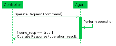
7.7.2 Asynchronous Operations
An asynchronous operation expects to take some processing on the
system the Agent represents and will return results at a later time.
When complete, the output arguments are sent in a Notify
(OperationComplete) request to any Controllers that have an
active subscription to the operation and Object(s) to which it
applies.
When a Controller using the Operate request specifies an operation
that is defined as asynchronous, the Agent creates an instance of the
Request Object in its data model, and includes a reference to the
created Object in the Operate response. If the send_resp
flag is false, the Controller doesn’t need the Request
details, and intends to ignore it.
The lifetime of a Request Object expires when the operation is complete (either by success or failure). An expired Request Object is removed from the Instantiated Data Model.
R-OPR.0 - When an Agent receives an Operate Request that addresses an asynchronous operation, it MUST create a Request Object in the Request table of its Instantiated Data Model (see the Device:2 Data Model [3]). When the Operation is complete (either success or failure), it MUST remove this Object from the Request table.
If any Controller wants a notification that an operation has
completed, it creates a Subscription Object with the
NotificationType set to OperationComplete and
with the ReferenceList Parameter including a Path Name to
the specified command. The Agent processes this Subscription when the
operation completes and sends a Notify Message, including the
command_key value that the Controller assigned when making
the Operate request.
A Controller can cancel a request that is still present in the
Agent’s Device.LocalAgent.Request. table by invoking the
Device.LocalAgent.Request.{i}.Cancel() command through
another Operate Message.
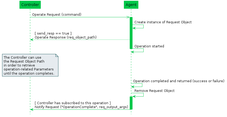
7.7.2.1 Persistence of Asynchronous Operations
Synchronous Operations do not persist across a reboot or restart of the Agent or its underlying system. It is expected that Asynchronous Operations do not persist, and a command that is in process when the Agent is rebooted can be expected to be removed from the Request table, and is considered to have failed. If a command is allowed or expected to be retained across a reboot, it will be noted in the command description.
7.7.3 Operate Requests on Multiple Objects
Since the Operate request can take a Path Name expression as a value
for the command field, it is possible to invoke the same operation on
multiple valid Objects as part of a single Operate request. Responses to
requests to Operate on more than one Object are handled using the
OperationResult field type, which is returned as a repeated
set in the Operate Response. The success or failure of the operation on
each Object is handled separately and returned in a different
OperationResult entry. For this reason, operation failures
are never conveyed in an Error Message - in reply to an Operate request,
Error is only used when the Message itself fails for one or more
reasons, rather than the operation invoked.
Note: This specification does not make any requirement on the order in which commands on multiple objects selected with a Path Name expression are executed.
R-OPR.1 - When processing Operate
Requests on multiple Objects, an Agent MUST NOT send an Error Message
due to a failed operation. It MUST instead include the failure in the
cmd_failure field of the Operate response.
R-OPR.2 - For asynchronous operations the Agent MUST create a separate Request Object for each Object and associated operation matched in the command field.
7.7.4 Event Notifications for Operations
When an operation triggers an Event notification, the Agent sends the Event notification for all subscribed recipients as described in Notifications and Subscription Mechanism.
7.7.5 Concurrent Operations
If an asynchronous operation is triggered multiple times by one or more Controllers, the Agent has the following options:
- Deny the new operation (with, for example,
7005 Resources Exceeded) - The operations are performed in parallel and independently.
- The operations are queued and completed in order.
R-OPR.3 - When handling
concurrently invoked operations, an Agent MUST NOT cancel an operation
already in progress unless explicitly told to do so by a Controller with
permission to do so (i.e., via the
Device.LocalAgent.Request.{i}.Cancel() operation).
7.7.6 Operate Examples
In this example of a synchronous command, the Controller requests
that the Agent initiate the SendOnBoardRequest() operation defined in
the Device.LocalAgent.Controller. Object.
header {
  msg_id: "42314"
  msg_type: OPERATE
}
body {
  request {
    operate {
      command: 'Device.LocalAgent.Controller.[EndpointID=="controller"].SendOnBoardRequest()'
      command_key: "onboard_command_key"
      send_resp: true
    }
  }
}
header {
msg_id: "42314"
msg_type: OPERATE_RESP
}
body {
response {
operate_resp {
operation_results {
executed_command: "Device.LocalAgent.Controller.1.SendOnBoardRequest()"
}
}
}
}In this example of an asynchronous command, the Controller requests
that the Agent initiate the SelfDiagnostics() operation defined in the
Device. object.
header {
  msg_id: "42315"
  msg_type: OPERATE
}
body {
  request {
    operate {
      command: 'Device.SelfTestDiagnostics()'
      command_key: "selftest_command_key"
      send_resp: true
    }
  }
}
header {
msg_id: "42315"
msg_type: OPERATE_RESP
}
body {
response {
operate_resp {
operation_results {
executed_command: "Device.SelfTestDiagnostics()"
req_obj_path: "Device.LocalAgent.Request.1."
}
}
}
}7.7.7 The Operate Message
7.7.7.1 Operate Request Fields
string command
This field contains a Command Path or Search Path to an Object defined Operation in one or more Objects.
string command_key
This field contains a string used as a reference by the Controller to match the operation with notifications.
bool send_resp
This field lets the Controller indicate to Agent whether or not it expects a response in association with the operation request.
R-OPR.4 - When
send_resp is set to false, the target Endpoint
SHOULD NOT send an OperateResp Message to the source
Endpoint. If an error occurs during the processing of an
Operate Message, the target Endpoint MAY send an
OperateResp Message to the source Endpoint containing
relevant cmd_failure elements. If a response is still sent,
the responding Endpoint MUST expect that any such response will be
ignored.
Note: The requirement in the previous versions of the
specification also discouraged the sending of an Error
Message, however the Controller issuing the Operate might
want to learn about and handle errors occurring during the processing of
the Operate request but still ignore execution
results.
map<string, string> input_args
This field contains a map of key/value pairs indicating the input arguments (relative to the Command Path in the command field) to be passed to the method indicated in the command field.
R-OPR.5 - A Command
can have mandatory input_args as defined in the Supported
Data Model. When a mandatory Input argument is omitted from the
input_args field, the Agent MUST, in its
OperateResp, include a cmd_failure element
containg an err_code of type 7027 Invalid
Command Arguments and stop processing the command.
R-OPR.6 - When an unrecognized
Input argument is included in the input_args field, the
Agent MUST ignore the Input argument and continue processing the
Operate Message.
R-OPR.7 - When a non-mandatory
Input argument is omitted from the input_args field, the
Agent MUST use a default value for the missing Input argument and
continue processing the Operate Message.
Refer to Parameter and Argument Value Encoding for details of how argument values are encoded as Protocol Buffers v3 strings.
7.7.7.2 Operate Response Fields
repeated OperationResult operation_results
This field contains a repeated set of OperationResult
messages.
7.7.7.2.1 OperationResult Fields
string executed_command
This field contains a Command Path to the Object defined Operation
that is the subject of this OperateResp message.
oneof operate_resp
This field contains a message of one of the following types.
  string req_obj_path
  OutputArgs req_output_args
  CommandFailure cmd_failure
7.7.7.2.1.1 Using req_obj_path
The req_obj_path field, when used as the operate_resp,
contains an Object Instance Path to the Request Object created as a
result of this asynchronous operation.
7.7.7.2.1.2 OutputArgs Fields
map<string, string> output_args
This field contains a map of key/value pairs indicating the output
arguments (relative to the command specified in the command
field) returned by the method invoked in the Operate Message. Refer to
Parameter and
Argument Value Encoding for details of how argument values are
encoded as Protocol Buffers v3 strings.
7.7.7.2.1.3 CommandFailure Fields
fixed32 err_code
This field contains a numeric code (see Error Codes) indicating the type of the error that caused the operation to fail.
string err_msg
This field contains additional (human readable) information about the reason behind the error.
7.7.7.3 Operate Message Error Codes
Appropriate error codes for the Operate Message include
7000-7008, 7016, 7022,
7026, 7027, and 7800-7999.
7.8 Error Codes
USP uses error codes with a range 7000-7999 for both Controller and Agent errors. The errors appropriate for each Message (and how they must be implemented) are defined in the message descriptions below.
| Code | Name | Applicability | Description |
|---|---|---|---|
7000 |
Message failed | Error Message | This error indicates a general failure that is described in an err_msg field. |
7001 |
Message not supported | Error Message | This error indicates that the attempted message was not understood by the target Endpoint. |
7002 |
Request denied (no reason specified) | Any | This error indicates that the target Endpoint cannot or will not process the message or operation. |
7003 |
Internal error | Any | This error indicates that the message or operation failed due to internal hardware or software reasons. |
7004 |
Invalid arguments | Any | This error indicates that the message or operation failed due to invalid values in the USP message. |
7005 |
Resources exceeded | Any | This error indicates that the message or operation failed due to memory or processing limitations on the target Endpoint. |
7006 |
Permission denied | Any | This error indicates that the source Endpoint does not have the authorization for this action. |
7007 |
Invalid configuration | Any | This error indicates that the message or operation failed because processing the message would put the target Endpoint in an invalid or unrecoverable state. |
7008 |
Invalid path syntax | Any requested_path | This error indicates that the Path Name used was not understood by the target Endpoint. |
7009 |
Parameter action failed | Set | This error indicates that the Parameter failed to update for a general reason described in an err_msg field. |
7010 |
Unsupported parameter | Add, Set | This error indicates that the requested Path Name associated with this ParamError or ParameterError did not match any instantiated Parameters. |
7011 |
Invalid type | Add, Set | This error indicates that the received string can not be interpreted as a value of the correct type expected for the Parameter. |
7012 |
Invalid value | Add, Set | This error indicates that the requested value was not within the acceptable values for the Parameter. |
7013 |
Attempt to update non-writeable parameter | Add, Set | This error indicates that the source Endpoint attempted to update a Parameter that is not defined as a writeable Parameter. |
7014 |
Value conflict | Add, Set | This error indicates that the requested value would result in an invalid configuration based on other Parameter values. |
7015 |
Operation error | Add, Set, Delete | This error indicates a general failure in the creation, update, or deletion of an Object that is described in an err_msg field. |
7016 |
Object does not exist | Any | This error indicates that the requested Path Name did not address an Object in the Agent’s Instantiated Data Model. |
7017 |
Object could not be created | Add | This error indicates that the operation failed to create an instance of the specified Object. |
7018 |
Object is not a table | Add, GetInstances | This error indicates that the requested Path Name is not a Multi-Instance Object. |
7019 |
Attempt to create non-creatable object | Add | This error indicates that the source Endpoint attempted to create an Object that is not defined as able to be created. |
7020 |
Object could not be updated | Set | This error indicates that the requested Object in a Set request failed to update. |
7021 |
Required parameter failed | Add, Set | This error indicates that the request failed on this Object because one or more required Parameters failed to update. Details on the failed Parameters are included in an associated ParamError or ParameterError message. |
7022 |
Command failure | Operate | This error indicates that an command initiated in an Operate Request failed to complete for one or more reasons explained in the err_msg field. |
7023 |
Command canceled | Operate | This error indicates that an asynchronous command initiated in an Operate Request failed to complete because it was cancelled using the Cancel() operation. |
7024 |
Delete failure | Delete | This error indicates that this Object Instance failed to be deleted. |
7025 |
Object exists with duplicate key | Add, Set | This error indicates that an Object already exists with the Unique Keys specified in an Add or Set Message. |
7026 |
Invalid path | Any | This error indicates that the Object, Parameter, or Command Path Name specified does not match any Objects, Parameters, or Commands in the Agent’s Supported Data Model |
7027 |
Invalid command arguments | Operate | This error indicates that an Operate Message failed due to invalid or unknown arguments specified in the command. |
7028 |
Register failure | Register | This error indicates that a path in a Register Request failed to be registered for one or more reasons explained in the err_msg field. |
7029 |
Already in use | Register | This error indicates that a path in a Register Request failed to be registered, because it was registered by a different USP Agent |
7030 |
Deregister failure | Deregister | This error indicates that a path in a Deregister Request failed to be deregistered for one or more reasons explained in the err_msg field. |
7031 |
Path already registered | Deregister | This error indicates that a path in a Deregister Request failed to be deregistered, because it was registered by a different USP Agent. |
7100-7199 |
USP Record error codes | - | These errors are listed and described in USP Record Errors. |
7200-7299 |
Data model defined error codes | - | These errors are described in the data model. |
7800-7999 |
Vendor defined error codes | - | These errors are described in Vendor Defined Error Codes. |
7.8.1 Vendor Defined Error Codes
Implementations of USP MAY specify their own error codes for use with
Errors and Responses. These codes use the 7800-7999 series.
There are no requirements on the content of these errors.
8 Authentication and Authorization
USP contains mechanisms for Authentication and Authorization, and Encryption. Encryption can be provided at the MTP layer, the USP layer, or both. Where Endpoints can determine (through Authentication) that the termination points of the MTP and USP messages are the same, MTP encryption is sufficient to provide end-to-end encryption and security. Where the termination points are different (because there is a proxy or other intermediate device between the USP Endpoints), USP layer End to End Message Exchange is required, or the intermediate device must be a trusted part of the end-to-end ecosystem.
8.1 Authentication
Authentication of Controllers is done using X.509 certificates as defined in [19] and [26] or shared secrets when using a UDS MTP. Authentication of Agents is done either by using X.509 certificates or shared secrets. X.509 certificates, at a minimum, need to be usable for Securing MTPs with TLS or DTLS protocols. It is recommended that Agents implement the ability to encrypt all MTPs using one of these two protocols, enable it by default, and not implement the ability to disable it.
In order to support various authentication models (e.g., trust
Endpoint identity and associated certificate on first use; precise
Endpoint identity is indicated in a certificate issued by a trusted
Certificate Authority; trust that MTP connection is being made to a
member of a trusted domain as verified by a trusted Certificate
Authority (CA)), this specification provides guidance based on
conditions under which the Endpoint is operating, and on the Endpoint’s
policy for storing certificates of other Endpoints or certificates of
trusted CAs. The Device.LocalAgent.Certificate. Object can
be implemented if choosing to expose these stored certificates through
the data model. See the Theory of Operations, Certificate
Management subsection, below for additional information.
R-SEC.0 - Prior to processing a USP Message from a Controller, the Agent MUST either:
- have the Controller’s certificate information and have a cryptographically protected connection between the two Endpoints, or
- have a Trusted Broker’s certificate information and have a cryptographically protected connection between the Agent and the Trusted Broker
- If using a UDS MTP, provide a shared secret to the Controller to authenticate it when the UDS connection requires password authentication.
R-SEC.0a - Whenever a X.509
certificate is used to authenticate a USP Endpoint, the certificate MUST
contain a representation of the Endpoint ID in the
subjectAltName extension. This representation MUST be
either the URN form of the Endpoint ID with a type
uniformResourceIdentifier attribute OR, in the specific
case where the Endpoint ID has an authority-scheme of
fqdn, the instance-id portion of the Endpoint
ID with a type dNSName attribute. When this type of
authentication is used at the MTP layer, USP Endpoints MUST check the
from_id field of received USP Records and MUST NOT process
Records that do not match the Endpoint ID found in the certificate.
TLS and DTLS both have handshake mechanisms that allow for exchange
of certificate information. If the MTP connection is between the Agent
and Controller (for example, without going through any application-layer
proxy or other intermediate application-layer middle-box), then a secure
MTP connection will be sufficient to ensure end-to-end protection, and
the USP Record can use payload_security “PLAINTEXT”
encoding of the Message. If the middle-box is part of a trusted
end-to-end ecosystem, the MTP connection may also be considered
sufficient. Otherwise, the USP Record will use End to End Message
Exchange.
Whether a Controller requires Agent certificates is left up to the Controller implementation.
8.2 Role Based Access Control (RBAC)
It is expected that Agents will have some sort of Access Control List (ACL) that will define different levels of authorization for interacting with the Agent’s data model. This specification refers to different levels of authorization as “Roles”. The Agent may be so simple as to only support a single Role that gives full access to its data model; or it may have just an “untrusted” Role and a “full access” Role. Or it may be significantly more complex with, for example, “untrusted” Role, different Roles for parents and children in a customer household, and a different Role for the service provider Controller. These Roles may be fully defined in the Agent’s code, or Role definition may be allowed via the data model.
R-SEC.1 - An Agent MUST confirm a Controller has the necessary permissions to perform the requested actions in a Message prior to performing that action.
R-SEC.1a - Agents SHOULD
implement the Controller Object with the
AssignedRole Parameter (with at least read-only data model
definition) and InheritedRole Parameter (if allowed Roles
can come from a trusted CA), so users can see what Controllers have
access to the Agent and their permissions. This will help users identify
rogue Controllers that may have gained access to the Agent.
See the Theory of Operations, Roles (Access Control) and Assigning Controller Roles subsections, below for additional information on data model elements that can be implemented to expose information and allow control of Role definition and assignment.
8.3 Trusted Certificate Authorities
An Endpoint can have a configured list of trusted Certificate Authority (CA) certificates. The Agent policy may trust the CA to authorize authenticated Controllers to have a specific default Role, or the policy may only trust the CA to authenticate the Controller identity. The Controller policy may require an Agent certificate to be signed by a trusted CA before the Controller exchanges USP Messages with the Agent.
R-SEC.2 - To confirm a certificate was signed by a trusted CA, the Endpoint MUST contain information from one or more trusted CA certificates that are either pre-loaded in the Endpoint or provided to the Endpoint by a secure means. At a minimum, this stored information will include a certificate fingerprint and fingerprint algorithm used to generate the fingerprint. The stored information MAY be the entire certificate.
This secure means can be accomplished through USP (see Theory of
Operations), Certificate Management subsection, making use of the
Device.LocalAgent.Certificate. Object), or through a
mechanism external to USP. The stored CA certificates can be root or
intermediate CAs.
R-SEC.3 - Where a CA is trusted to authenticate Controller identity, the Agent MUST ensure that the Controller certificate conforms with the R-SEC.0a requirement.
R-SEC.4 - Where a CA is trusted
to authorize a Controller Role, the Agent MUST ensure either that the
Controller certificate matches the certificate stored in the
Credential Parameter of the
Device.LocalAgent.Controller. entry specific to that
Controller OR that the Controller certificate itself is suitable for
authentication as per the R-SEC.0a requirement.
Note that trusting a CA to authorize a Controller Role requires the
Agent to maintain an association between a CA certificate and the
Role(s) that CA is trusted to authorize. If the Agent allows CAs to
authorize Roles, the Agent will need to identify specific CA
certificates in a Controller’s chain of trust that can authorize Roles.
The specific Role(s) associated with such a CA certificate can then be
inherited by the Controller. The
Device.LocalAgent.ControllerTrust.Credential. Object can be
implemented to expose and allow control over trust and authorization of
CAs.
Note that if an Agent supports and has enabled a Trust on First Use (TOFU) policy, it is possible for Controllers signed by unknown CAs to be granted the “untrusted role”. See Figure 23 and Figure 24 and the penultimate bullet in the Assigning Controller Roles section below for more information related to TOFU and the “untrusted” role.
8.4 Trusted Brokers
An Endpoint can have a configured list of Trusted Broker
certificates. The Endpoint policy would be to trust the broker to vouch
for the identity of Endpoints it brokers – effectively authenticating
the from_id contained in a received USP Record. The Agent
policy may trust the broker to authorize all Controllers whose Records
transit the broker to have a specific default Role.
R-SEC.4a - To confirm a certificate belongs to a Trusted Broker, the Endpoint MUST contain information from one or more Trusted Broker certificates that are either pre-loaded in the Endpoint or provided to the Endpoint by a secure means. This stored information MUST be sufficient to determine if a presented certificate is the Trusted Broker certificate.
This secure means of loading certificate information into an Agent can be accomplished through USP (see Theory of Operations section related to Certificate Management), or through a mechanism external to USP.
Note that trusting a broker to authorize a Controller Role requires
the Agent to maintain an association between a Trusted Broker
certificate and the Role(s) that Trusted Broker is trusted to authorize.
The Device.LocalAgent.ControllerTrust.Credential. Object
can be implemented to expose and allow control over identifying Trusted
Brokers. The AllowedUses Parameter is used to indicate
whether an entry is a Trusted Broker.
R-SEC.4b - A Trusted Broker MUST confirm the identity of all clients by exclusively allowing authentication via unique client certificates that identify the USP Endpoint. Also the confidentiality of all communications MUST be guaranteed by a Trusted Broker, i.e. there MUST NOT be any possibility to forward the communication between Endpoints to another party.
R-SEC.4c - A Trusted Broker MUST
guarantee that USP Records sent from clients contain the correct value
for the from_id field, tying it to the identity provided
during the connection establishment. A Trusted Broker MUST NOT inspect
USP payloads contained in USP Records.
8.5 Self-Signed Certificates
R-SEC.5 - An Endpoint that generates a self-signed certificate MUST ensure that the certificate is suitable for USP authentication as per the R-SEC.0a requirement.
Self-signed certificates supplied by Controllers can only be meaningfully used in cases where a person is in a position to provide Authorization (what Role the Controller is trusted to have). Whether or not an Agent allows self-signed certificates from a Controller is a matter of Agent policy.
R-SEC.6 - If an Agent allows Controllers to provide self-signed certificates, the Agent MUST assign such Controllers an “untrusted” Role on first use.
That is, the Agent will trust the certificate for purpose of encryption, but will heavily restrict what the Controller is authorized to do. See Figure 23 and Figure 24 and the penultimate bullet in the Assigning Controller Roles section below for more information related to TOFU and the “untrusted” role.
R-SEC.7 - If an Agent allows Controllers to provide self-signed certificates, the Agent MUST have a means of allowing an external entity to change the Role of each such Controller.
Controller policy related to trust of Agent self-signed certificates is left to the Controller. Controllers may be designed to refuse self-signed certificates (thereby refusing to control the Agent), they may have a means of allowing a person to approve controlling the Agent via the Controller, or they may automatically accept the Agent.
R-SEC.8 - An Endpoint that accepts self-signed certificates MUST maintain the association of accepted certificate and Endpoint IDs.
Self-signed certificates require a “trust on first use” (TOFU) policy
when using them to authenticate an Endpoint’s identity. An external
entity (a trusted Controller or user) can then authorize the
authenticated Endpoint to have certain permissions. Subsequent to the
first use, this same self-signed certificate can be trusted to establish
the identity of that Endpoint. However, authentication of the Endpoint
can only be subsequently trusted if the association of certificate to
identity is remembered (i.e., it is known this is the same certificate
that was used previously by that Endpoint). If it is not remembered,
then every use is effectively a first use and would need to rely on an
external entity to authorize permissions every time. The
Device.LocalAgent.Certificate. Object can be implemented if
choosing to expose and allow control of remembered certificates in the
data model.
8.6 Agent Authentication
R-SEC.9 - Controllers MUST authenticate Agents either through X.509 certificates, a shared secret, or by trusting a Trusted Broker to vouch for Agent identity.
When authentication is done using X.509 certificates, it is up to Controller policy whether to allow for Agents with self-signed certificates or to require Agent certificates be signed by a CA.
Note that allowing use of, method for transmitting, and procedure for handling shared secrets is specific to the MTP used, as described in Message Transfer Protocols. Shared secrets that are not unique per device are not recommended as they leave devices highly vulnerable to various attacks – especially devices exposed to the Internet.
R-SEC.10 - An Agent certificate MUST be suitable for USP authentication as per the R-SEC.0a requirement.
R-SEC.10a - The certificate
subjectAltName extension MUST be used to authenticate the
USP Record from_id for any Records secured with an Agent
certificate.
Agent certificates can be used to secure Records by encrypting at the MTP layer and/or encrypting at the USP layer.
Some Controller implementations may allow multiple Agents to share a single certificate with a wildcarded Endpoint ID.
R-SEC.11 - If a single
certificate is shared among multiple Agents, those Agents MUST include a
wild-carded instance-id in the Endpoint ID in the
subjectAltName extension with identical
authority-scheme and authority-id.
Use of a shared certificate is not recommended, and which portion of
the instance-id can be wildcarded may be specific to the
authorizing CA or to the authority-id and
authority-scheme values of the Endpoint ID. Wildcards can
only be allowed in cases where the assigning entity is explicitly
identified. Controllers are not required to support wildcarded
certificates.
R-SEC.12 - If a wildcard
character is present in the instance-id of an Endpoint ID
in a certificate subjectAltName extension, the
authority-scheme MUST be one of “oui”, “cid”, “pen”, “os”,
or “ops”. In the case of “os” and “ops”, the portion of the
instance-id that identifies the assigning entity MUST NOT
be wildcarded.
8.7 Challenge Strings and Images
It is possible for the Agent to allow an external entity to change a Controller Role by means of a Challenge string or image. This Challenge string or image can take various forms, including having a user supply a passphrase or a PIN. Such a string could be printed on the Agent packaging, or supplied by means of a SMS to a phone number associated with the user account. These Challenge strings or images can be done using USP operations. Independent of how challenges are accomplished, following are some basic requirements related to Challenge strings and images.
R-SEC.13 - The Agent MAY have factory-default Challenge value(s) (strings or images) in its configuration.
R-SEC.14 - A factory-default Challenge value MUST be unique to the Agent. Re-using the same passphrase among multiple Agents is not permitted.
R-SEC.15 - A factory-default Challenge value MUST NOT be derivable from information the Agent communicates about itself using any protocol at any layer.
R-SEC.16 - The Agent MUST limit the number of tries for the Challenge value to be supplied successfully.
R-SEC.17 - The Agent SHOULD have policy to lock out all use of Challenge values for some time, or indefinitely, if the number of tries limit is exceeded.
See the Theory of Operations, Challenges subsection, below for a description of data model elements that need to be implemented and are used when doing challenges through USP operations.
8.8 Analysis of Controller Certificates
An Agent will analyze Controller certificates to determine if they are valid, are appropriate for authentication of Controllers, and to determine what permissions (Role) a Controller has. The Agent will also determine whether MTP encryption is sufficient to provide end-to-end protection of the Record and Message, or if USP layer End to End Message Exchange is required.
The diagrams in this section use the database symbol to identify where the described information can be represented in the data model, if an implementation chooses to expose this information through the USP protocol.
8.8.1 Receiving a USP Record
R-SEC.19 - An Agent capable of obtaining absolute time SHOULD wait until it has accurate absolute time before contacting a Controller. If an Agent for any reason is unable to obtain absolute time, it can contact the Controller without waiting for accurate absolute time. If an Agent chooses to contact a Controller before it has accurate absolute time (or if it does not support absolute time), it MUST ignore those components of the Controller certificate that involve absolute time, e.g. not-valid-before and not-valid-after certificate restrictions.
R-SEC.20 - An Agent that has obtained accurate absolute time MUST validate those components of the Controller certificate that involve absolute time.
R-SEC.21 – An Agent MUST clear all cached encryption session and Role authorization information when it reboots.
R-SEC.22 - When an Agent receives a USP Record, the Agent MUST execute logic that achieves the same results as in the mandatory decision flow elements (identified with “MUST”) from Figure 20 and Figure 21.
R-SEC.22a - When an Agent receives a USP Record, the Agent SHOULD execute logic that achieves the same results as in the optional decision flow elements (identified with “OPT”) from Figure 20 and Figure 21.
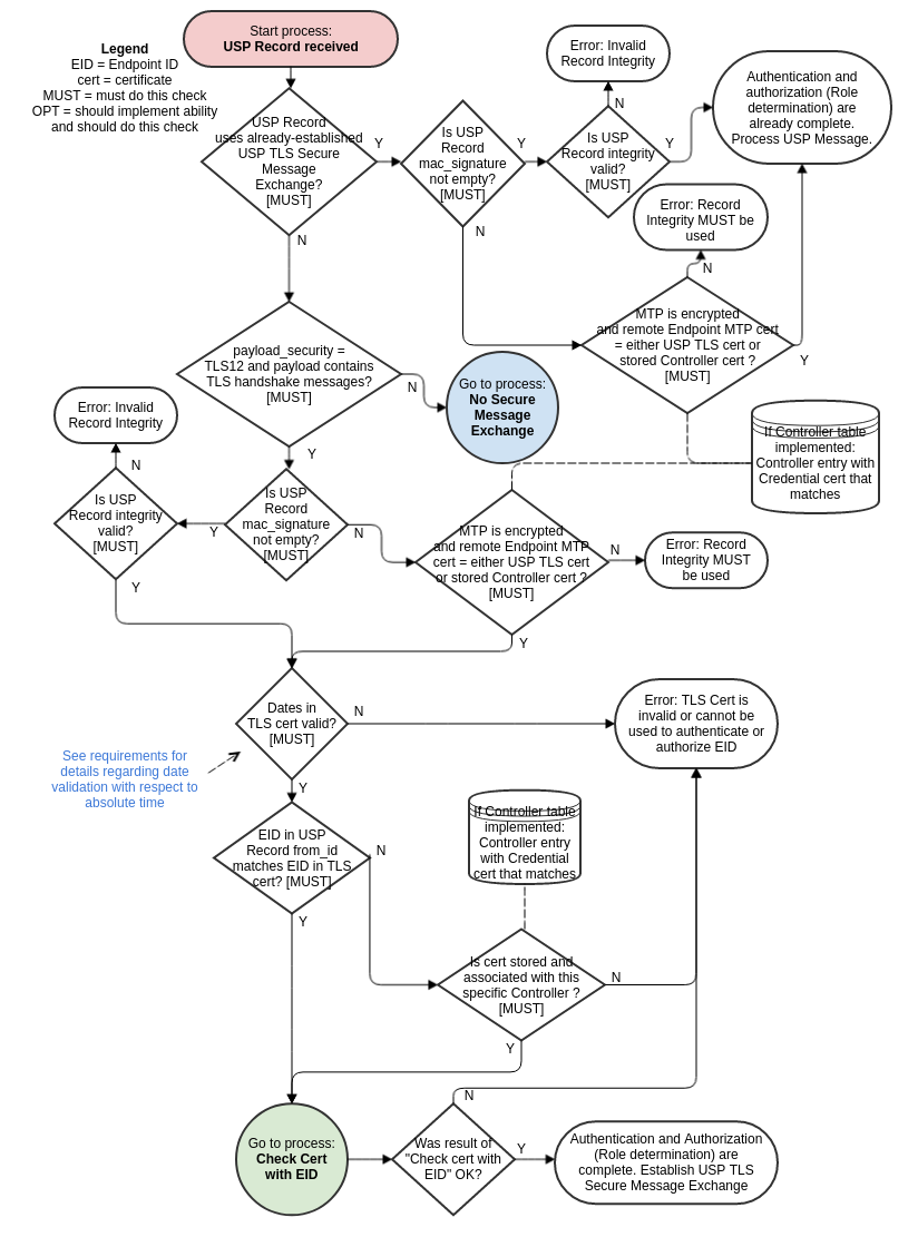
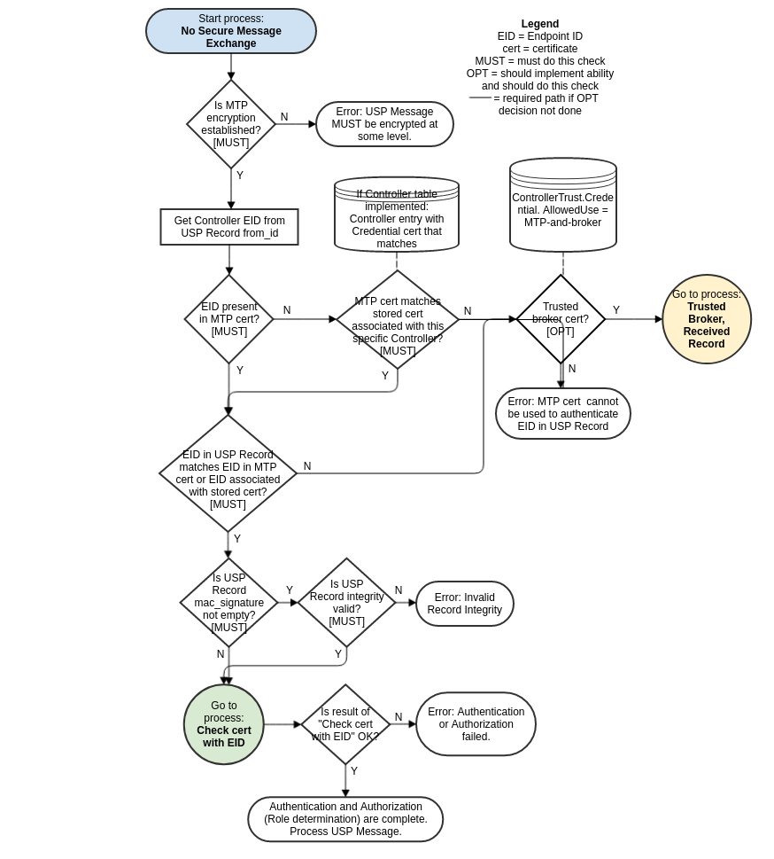
8.8.2 Sending a USP Record
R-SEC.23 - When an Agent sends a USP Record, the Agent MUST execute logic that achieves the same results as in the mandatory decision flow elements (identified with “MUST”) from Figure 22.
R-SEC.23a - When an Agent sends a USP Record, the Agent SHOULD execute logic that achieves the same results as in the optional decision flow elements (identified with “OPT”) from Figure 22.
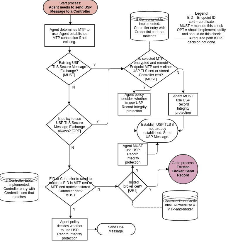
8.8.3 Checking a Certificate
R-SEC.24 - When an Agent analyzes a Controller certificate for authentication and determining permissions (Role), the Agent MUST execute logic that achieves the same results as in the mandatory decision flow elements (identified with “MUST”) from Figure 23 and Figure 24.
R-SEC.24a - When an Agent analyzes a Controller certificate for authentication and determining permissions (Role), the Agent SHOULD execute logic that achieves the same results as in the optional decision flow elements (identified with “OPT”) from Figure 23 and Figure 24.
R-SEC.25 - When determining the inherited Role to apply based on Roles associated with a trusted CA, only the first matching CA in the chain will be used.
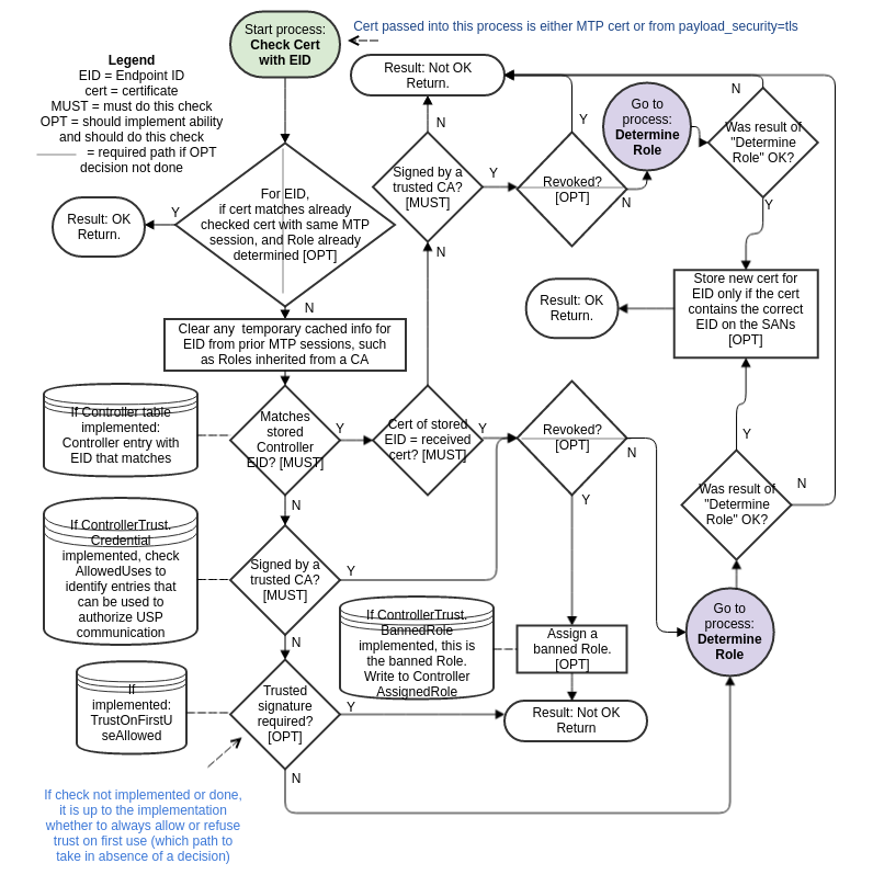
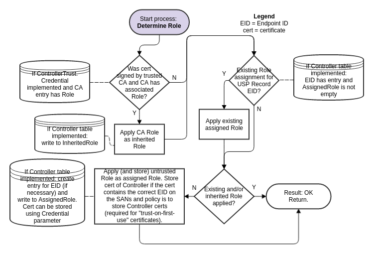
8.8.4 Using a Trusted Broker
Support for Trusted Broker logic is optional.
R-SEC.26 - If Trusted Brokers are supported, and a Trusted Broker is encountered (from the optional “OPT” “Trusted Broker cert?” decision diamonds in Figure 21, Figure 22) the Agent MUST execute logic that achieves the same results as in the mandatory decision flow elements (identified with “MUST”) from Figure 25 for a received USP Record and Figure 26 for sending a USP Record.
R-SEC.26a - If Trusted Brokers are supported, and a Trusted Broker is encountered (from the optional “OPT” “Trusted Broker cert?” decision diamonds in Figure 21, Figure 22) the Agent SHOULD execute logic that achieves the same results as in the optional decision flow elements (identified with “OPT”) from Figure 25 for a received USP Record and Figure 26 for sending a USP Record.
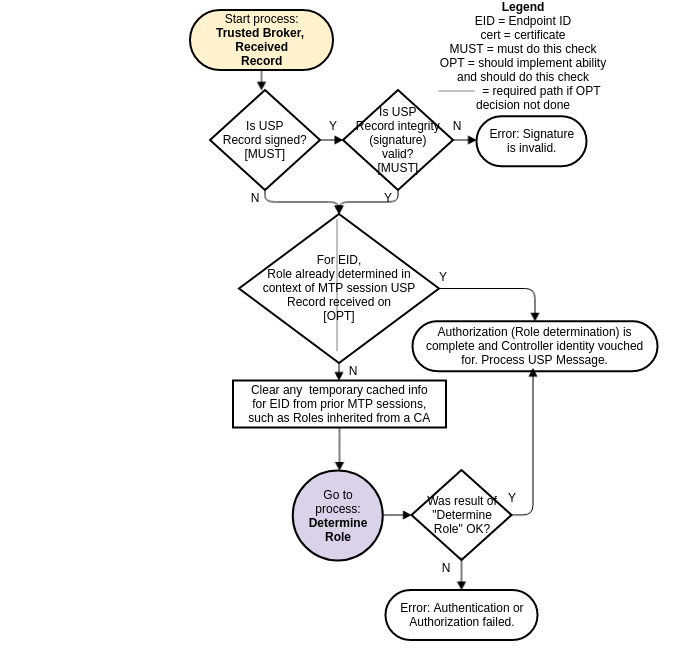
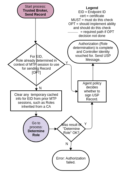
8.9 Theory of Operations
The following theory of operations relies on Objects, Parameters,
events, and operations from the LocalAgent Object of the
Device:2 Data Model [3].
8.9.1 Data Model Elements
These data model elements play a role in reporting on and allowing control of trusted Controllers and the permissions they have to read and write parts of the Agent’s data model, and allowing an Agent to establish trust with a Controller.
LocalAgent.Controller.{i}.AssignedRoleParameterLocalAgent.Controller.{i}.InheritedRoleParameterLocalAgent.Controller.{i}.CredentialParameter
From component ControllerTrust:
- Object
LocalAgent.ControllerTrust. - Parameters
UntrustedRole,BannedRole,SecuredRoles,TOFUAllowed,TOFUInactivityTimer - Commands
RequestChallenge(),ChallengeResponse() - Object
LocalAgent.ControllerTrust.Role.{i}. - Object
LocalAgent.ControllerTrust.Credential.{i}. - Object
LocalAgent.ControllerTrust.Challenge.{i}.
The Object LocalAgent.Certificate. can be used to manage
Controller and CA certificates, along with the
LocalAgent.AddCertificate() and
LocalAgent.Controller.{i}.AddMyCertificate() commands.
For brevity, Device.LocalAgent. is not placed in front
of all further Object references in this Security section. However, all
Objects references are under Device.LocalAgent.. This
section does not describe use of Parameters under other top level
components.
8.9.2 Roles (Access Control)
Controller permissions are conveyed in the data model through Roles.
8.9.2.1 Role Definition
A Role is described in the data model through use of the
ControllerTrust.Role.{i}. Object. Each entry in this Object
identifies the Role it describes, and has a Permission.
Sub-Object for the Targets (data model Path Names that the
related permissions apply to), permissions related to Parameters,
Objects, instantiated Objects, and commands identified by the
Targets Parameter, and the relative Order of
precedence among Permission. entries for the Role (the
larger value of this Parameter takes priority over an entry with a
smaller value in the case of overlapping Targets entries
for the Role).
The permissions of a Role for the specified Target
entries are described by Param, Obj,
InstantiatedObj, and CommandEvent Parameters.
Each of these is expressed as a string of 4 characters where each
character represents a permission (“r” for Read,
“w” for Write, “x” for Execute”, and
“n” for Notify). The 4 characters are always presented in
the same order in the string (rwxn) and the lack of a
permission is signified by a “-” character (e.g.,
r--n). How these permissions are applied to the data model,
be it the Supported Data Model or the Instantiated Data Model, is
described in the data model description of these Parameters, Objects,
and various Messages.
An Agent that wants to allow Controllers to define and modify Roles
will implement the ControllerTrust.Role.{i}. Object with
all of the Parameters listed in the data model. In order for a
Controller to define or modify Role entries, it will need to be assigned
a Role that gives it the necessary permission. Care should be taken to
avoid defining this Role’s permissions such that an Agent with this Role
can modify the Role and no longer make future modifications to the
ControllerTrust.Role.{i}. Object.
A simple Agent that only wants to inform Controllers of pre-defined
Roles (with no ability to modify or define additional Roles) can
implement the ControllerTrust.Role. Object with read-only
data model definition for all entries and Parameters. A simple Agent
could even implement the Object with read-only data model definition and
just the Alias and Role Parameters, and no
Permission. Sub-Object; this could be sufficient in a case
where the Role names convey enough information (e.g., there are only two
pre-defined Roles named "Untrusted" and
"FullAccess").
In this example, the device is configured with a single role that allows a Controller to access the entire Data Model.
Device.LocalAgent.ControllerTrust.Role.1.Permission.1.Order = 1
Device.LocalAgent.ControllerTrust.Role.1.Permission.1.Targets = Device
Device.LocalAgent.ControllerTrust.Role.1.Permission.1.Param = rwxn
Device.LocalAgent.ControllerTrust.Role.1.Permission.1.Obj = rwxn
Device.LocalAgent.ControllerTrust.Role.1.Permission.1.InstantiatedObj = rwxn
Device.LocalAgent.ControllerTrust.Role.1.Permission.1.CommandEvent = rwxn
The next example builds upon the previous example where the device
was configured with a role that allows a Controller to access the entire
Data Model (Permission.1), but in this example there is an
exception added that prevents the Controller from accessing the
LocalAgent.ControllerTrust portion of the Data Model
(Permission.2). The reason this works is due to the Order
parameter. Since the Order parameter in the Permission.2
instance (value of 2) is larger than (higher priority) the Order
parameter in the Permission.1 instance (value of 1),
Permission.2 is applied on top of
Permission.1.
Device.LocalAgent.ControllerTrust.Role.1.Permission.2.Order = 2
Device.LocalAgent.ControllerTrust.Role.1.Permission.2.Targets = Device.LocalAgent.ControllerTrust
Device.LocalAgent.ControllerTrust.Role.1.Permission.2.Param = ----
Device.LocalAgent.ControllerTrust.Role.1.Permission.2.Obj = ----
Device.LocalAgent.ControllerTrust.Role.1.Permission.2.InstantiatedObj = ----
Device.LocalAgent.ControllerTrust.Role.1.Permission.2.CommandEvent = ----
Conversely, that role could have been configured to allow access to
the permissions, but not allowed access to read, write, or receive
ValueChange notifications for the Order parameter.
Device.LocalAgent.ControllerTrust.Role.1.Permission.2.Order = 2
Device.LocalAgent.ControllerTrust.Role.1.Permission.2.Targets = Device.LocalAgent.ControllerTrust.Role.*.Permission.*.Order
Device.LocalAgent.ControllerTrust.Role.1.Permission.2.Param = ----
Device.LocalAgent.ControllerTrust.Role.1.Permission.2.Obj = rwxn
Device.LocalAgent.ControllerTrust.Role.1.Permission.2.InstantiatedObj = rwxn
Device.LocalAgent.ControllerTrust.Role.1.Permission.2.CommandEvent = rwxn
Based on the above example device settings, if a Controller was
assigned the previously defined role and it attempted to perform an Add
operation on the Permission table where param_settings included the
Order parameter as a required setting, the Add operation
would fail because the Controller does not have write permissions for
the Order parameter.
 add {
     allow_partial: false
     create_objs {
        obj_path: "Device.LocalAgent.ControllerTrust.Role.1.Permission."
        param_settings {
          param: "Order"
          value: "12"
          required: true
        }
      }
    }
Now, if that same Controller attempted to perform that Add operation
on the Permission table but this time the param_settings included the
Order parameter as a non-required setting, the Add
operation would NOT fail due to the lack of write permissions for the
Order parameter, instead the value requested for the
Order parameter would be ignored.
 add {
     allow_partial: false
      create_objs {
        obj_path: "Device.LocalAgent.ControllerTrust.Role.1.Permission."
        param_settings {
          param: "Order"
          value: "12"
          required: false
       }
     }
    }
8.9.2.2 Special Roles
Three special Roles are identified by the UntrustedRole,
BannedRole and SecuredRoles Parameters under
the ControllerTrust. Object. An Agent can expose these
Parameters with read-only data model implementation if it simply wants
to tell Controllers the names of these specific Roles.
The UntrustedRole is the Role the Agent will
automatically assign to any Controller that has not been authorized for
a different Role. Any Agent that has a means of allowing a Controller’s
Role to be changed (by users through a Challenge string, by other
Controllers through modification of
Controller.{i}.AssignedRole, or through some other external
means) and that allows “unknown” Controllers to attach will need to have
an “untrusted” Role defined; even if the identity of this Role is not
exposed to Controllers through implementation of the
UntrustedRole Parameter.
The BannedRole (if implemented) is assigned
automatically by the Agent to Controllers whose certificates have been
revoked. If it is not implemented, the Agent can use the
UntrustedRole for this, as well. It is also possible to
simply implement policy for treatment of invalid or revoked certificates
(e.g., refuse to connect), rather than associate them with a specific
Role. This is left to the Agent policy implementation.
The SecuredRoles (if implemented) is the Role assigned
to Controllers that are authorized to have access to
secured Parameter values. If the SecuredRoles
is not assigned to a given Controller, or if the
SecuredRoles is not implemented, then secured
Parameters are to be considered as hidden, in which case
the Agent returns a null value, e.g. an empty string, to this
Controller, regardless of the actual value. Only Controllers with a
secured Role assigned (and the appropriate permissions set), are able to
have access to secured parameter values. When the
SecuredRoles Parameter references an instance of the Role
table containing a Target with a Partial Path, then any included
Parameters that are not identified as secured will be
ignored. The Agent will have access to all secured
parameters in that path.
For example, if a Controller needed access to all
secured Parameters in the Data Model, then the
SecuredRoles Parameter could be set to the role that was
defined in the previous example:
Device.LocalAgent.ControllerTrust.SecuredRoles = Device.LocalAgent.ControllerTrust.Role.18.9.2.3 A Controller’s Role
A Controller’s assigned Roles can be conveyed by the
Controller.{i}.AssignedRole Parameter. This Parameter is a
list of all Role values assigned to the Controller through means other
than ControllerTrust.Credential.{i}.Role. A Controller’s
inherited Roles (those inherited from
ControllerTrust.Credential.{i}.Role as described in the
next section) need to be maintained separately from assigned Roles and
can be conveyed by the Controller.{i}.InheritedRole
Parameter. Where multiple assigned and inherited Roles have overlapping
Targets entries, the resulting permission is the union of
all assigned and inherited permissions. For example, if two Roles have
the same Targets with one Role assigning the
Targets Param a value of r--- and
the other Role assigning Param a value of
---n, the resulting permission will be r--n.
This is done after determining which
ControllerTrust.Role.{i}.Permission.{i} entry to apply for
each Role for specific Targets, in the case where a Role
has overlapping Permission.{i}.Targets entries for the same
Role.
For example, Given the following
ControllerTrust.Role.{i}. entries:
  i=1, Role = "A"; Permission.1.: Targets = "Device.LocalAgent", Order = 3, Param = "r---"
  i=1, Role = "A"; Permission.2.: Targets = "Device.LocalAgent.Controller", Order = 55, Param = "r-xn"
  i=3, Role = "B"; Permission.1.: Targets = "Device.LocalAgent", Order = 20, Param = "r---"
  i=3, Role = "B"; Permission.5.: Targets = "Device.LocalAgent.Controller", Order = 78, Param = "----"
and Device.LocalAgent.Controller.1.AssignedRole =
"Device.LocalAgent.ControllerTrust.Role.1", "Device.LocalAgent. ControllerTrust.Role.3"
When determining permissions for the
Device.LocalAgent.Controller. table, the Agent will first
determine that for Role A Permission.2 takes precedence
over Permission.1 (55 > 3). For B,
Permission.5 takes precedence over
Permission.1 (78 > 20). The union of A and B is
r-xn + ---- = r-xn.
8.9.2.4 Role Associated with a Credential or Challenge
The ControllerTrust.Credential.{i}.Role Parameter value
is inherited by Controllers whose credentials have been validated using
the credentials in the same entry of the
ControllerTrust.Credential.{i}. table. Whenever
ControllerTrust.Credential.{i}. is used to validate a
certificate, the Agent writes the current value of the associated
ControllerTrust.Credential.{i}.Role into the
Controller.{i}.InheritedRole Parameter. For more
information on use of this table for assigning Controller Roles and
validating credentials, see the sections below.
The ControllerTrust.Challenge.{i}.Role Parameter is a
Role that is assigned to Controllers that send a successful
ChallengeResponse() command. For more information on use of
challenges for assigning Controller Roles, see the sections below.
8.9.3 Assigning Controller Roles
As mentioned above, the Controller.{i}.AssignedRole
Parameter can be used to expose the Controller’s assigned Role via the
data model.
Note: Even if it is not exposed through the data model, the Agent is expected to maintain knowledge of the permissions assigned to each known Controller.
Controllers can be assigned Roles through a variety of methods,
depending on the data model elements an Agent implements and the Agent’s
coded policy. Note that it is possible for an Agent to maintain trusted
CA credentials with associated permissions (as described by the
ControllerTrust.Credential.{i}. Object) and various default
permission definitions (as identified by the UntrustedRole
and BannedRole Parameters) without exposing these through
the data model. If the data is maintained but not exposed, the same
methods can still be used.
Figure 23 and Figure 24 in the above Analysis of Controller Certificates section identify points in the decision logic where some of the following calls to data model Parameters can be made. The following bullets note when they are identified in one of these figures.
Another Controller (with appropriate permission) can insert a Controller (including the
AssignedRoleParameter value) into theController.{i}.table, or can modify theAssignedRoleParameter of an existingController.{i}.entry. TheInheritedRolevalue cannot be modified by another Controller.If credentials in an entry in a
ControllerTrust.Credential.{i}.CredentialParameter with an associatedControllerTrust.Credential.{i}.RoleParameter are used to successfully validate the certificate presented by the Controller, the Controller inherits the Role from the associatedControllerTrust.Credential.{i}.Role. The Agent writes this value to theController.{i}.InheritedRoleParameter. This step is shown in Figure 24.A Controller whose associated certificate is revoked by a CA can be assigned the role in
BannedRole, if this Parameter or policy is implemented. In this case, the value ofBannedRolemust be the only value inController.{i}.AssignedRole(all other entries are removed) andController.{i}.InheritedRolemust be empty (all entries are removed). This step is shown in Figure 23. In the case of a Controller that has not previously been assigned a Role or who has been assigned the value ofUntrustedRole:If the Controller’s certificate is validated by credentials in a
ControllerTrust.Credential.{i}.CredentialParameter but there is no associatedControllerTrust.Credential.{i}.RoleParameter (or the value is empty) andController.{i}.AssignedRoleis empty, then the Controller is assigned the role inUntrustedRole(written to theController.{i}.AssignedRoleParameter). This step is shown in Figure 24. Note that assigningUntrustedRolemeans there needs to be some implemented way to elevate the Controller’s Role, either by another Controller manipulating the Role, implementing Challenges, or some non-USP method.If the Controller’s certificate is self-signed or is validated by credentials not in
ControllerTrust.Credential.{i}., the Agent policy may be to assign the role inUntrustedRole. The optional policy decision (whether or not to allow Trust on First Use (TOFU), which can be codified in the data model with the ControllerTrust.TOFUAllowed flag) is shown in Figure 23; Figure 24 shows the Role assignment.If the Agent implements the
RequestChallenge()andChallengeResponse()commands, a Controller assigned the role inUntrustedRolecan have permission to read one or moreControllerTrust.Challenge.{i}.AliasandDescriptionvalues and issue the commands. Roles with more extensive permissions can have permission to read additionalControllerTrust.Challenge.{i}.AliasandDescriptionvalues. A successful Challenge results in the Controller being assigned the associated Role value.
8.9.4 Controller Certificates and Certificate Validation
When an Agent is presented with a Controller’s certificate, the Agent will always attempt to validate the certificate to whatever extent possible. Figure 21, Figure 23 and Figure 24 identify points in the decision logic where data model Parameters can be used to influence policy decisions related to Controller certificate analysis.
Note that it is possible for an Agent to maintain policy of the type
described by the UntrustedRole, BannedRole,
and the information described by
ControllerTrust.Credential.{i}. and
Controller.{i}.Credential without exposing these through
the data model. If the policy concepts and data are maintained but not
exposed, the same methods can still be used. It is also possible for an
Agent to have policy that is not described by any defined data model
element.
8.9.5 Challenges
An Agent can implement the ability to provide Controllers with challenges via USP, in order to be trusted with certain Roles. It is also possible to use non-USP methods to issue challenges, such as HTTP digest authentication with prompts for login and password.
To use the USP mechanism, the RequestChallenge() and
ChallengeResponse() commands and
ControllerTrust.Challenge.{i}. Object with at least the
Alias, Role, and Description
Parameters needs to be implemented. The functionality implied by the
other ControllerTrust.Challenge.{i}. Parameters needs to be
implemented, but does not have to be exposed through the data model.
A Controller that sends a Get Message on
Device.ControllerTrust.Challenge.{i}. will receive all
entries and Parameters that are allowed for its current assigned Role.
In the simplest case, this will be a single entry and only Alias and
Description will be supplied for that entry. It is important to restrict
visibility to all other implemented Parameters to highly trusted Roles,
if at all.
The Controller can display the value of Description to
the user and allow the user to indicate they want to request the
described challenge. If multiple entries were returned, the user can be
asked to select which challenge they want to request, based on the
description. An example of a description might be “Request
administrative privileges” or “Request guest privilege”.
When the user indicates to the Controller which challenge they want,
the Controller sends RequestChallenge() with the Path Name
of the Challenge Object Instance associated with the
desired Description. The Agent replies with the associated
Instruction, InstructionType,
ValueType and an auto-generated ChallengeID.
The Controller presents the value of Instruction to the
user (in a manner appropriate for InstructionType).
Examples of an instruction might be “Enter passphrase printed on bottom
of device” or “Enter PIN sent to registered email address”. The user
enters a string per the instructions, and the Controller sends this
value together with the ChallengeID in
ChallengeResponse().
If the returned value matches Value, the Agent gives a
successful response - otherwise it returns an unsuccessful response. If
successful, the ControllerTrust.Challenge.{i}.Role replaces
an UntrustedRole in
Controller.{i}.AssignedRole or is appended to any other
Controller.{i}.AssignedRole value.
The number of times a ControllerTrust.Challenge.{i}.
entry can be consecutively failed (across all Controllers, without
intermediate success) is defined by Retries. Once the
number of failed consecutive attempts equals Retries, the
ControllerTrust.Challenge.{i}. cannot be retried until
after LockoutPeriod has expired.
Type values other than Passphrase can be used and
defined to trigger custom mechanisms, such as requests for emailed or
SMS-provided PINs.
8.9.6 Certificate Management
If an Agent wants to allow certificates associated with Controllers
and CAs to be exposed through USP, the Agent can implement the
Controller.{i}.Credential and
ControllerTrust.Credential.{i}.Credential Parameters, which
require implementation of the LocalAgent.Certificate.
Object. Allowing management of these certificates through USP can be
accomplished by implementing LocalAgent.AddCertificate(),
Controller.{i}.AddMyCertificate() and
Certificate.{i}.Delete() commands.
To allow a Controller to check whether the Agent has correct
certificates, the Certificate.{i}.GetFingerprint() command
can be implemented.
8.9.7 Application of Modified Parameters
It is possible that various Parameters related to authentication and
authorization may change that would impact cached encrypted sessions and
Role permissions for Controllers. Example of such Parameters include
Controller.{i}.AssignedRole,
Controller.{i}.Credential,
ControllerTrust.Role. definition of a Role, and
ControllerTrust.Credential.{i}.Role.
There is no expectation that an Agent will apply these changes to cached sessions. It is up to the Agent to determine whether or not it will detect these changes and flush cached session information. However, it is expected that a reboot will clear all cached session information.
Annex A: Bulk Data Collection
Note: This Annex has been re-written in the 1.2 version of the USP specification to include the previously-defined USP Event Notification aspects of Bulk Data Collection and the new MQTT aspects of Bulk Data Collection, in addition to the already defined HTTP Bulk Data Collection mechanism.
This section discusses the Theory of Operation for USP specific mechanisms related to the collection and transfer of bulk data using either HTTP, MQTT, or USP Event Notifications. This includes an explanation of how the Agent can be configured to enable the collection of bulk data using HTTP, MQTT, or USP Event Notifications via the BulkData Objects, which are defined in the Device:2 Data Model [3].
A.1 Introduction
The general concept behind the USP Bulk Data collection mechanism is that a USP Controller can configure an Agent to consistently deliver a bulk data report at a specific interval. For large populations, this is a more efficient mechanism when compared to the alternative of polling each individual Agent for the data. There are four key aspects of configuring the bulk data collection mechanism on an Agent:
What data needs to be collected :: The set of Object/Parameter Path Names that dictate the set of Parameters that will be included in each Bulk Data report. Anything included in this set should be considered a filter that is applied against the Instantiated Data Model at the time of report generation, which means that the generation of the report is not contingent upon the Path Name being present in the Instantiated Data Model at the time of report generation.
How often does the data need to be collected :: The interval and time reference that dictates the frequency and cycle of report generation. For example, the interval could be set to 15 minutes while the time reference could be set to 42 minutes past 1 AM, which would mean that the report is generated every 15 minutes at 42 past the hour, 57 past the hour, 12 past the hour, and 27 past the hour.
Where does the data need to be sent :: The destination of where the report needs to be delivered after it has been generated. This is specific to the Bulk Data collection mechanism being used: HTTP vs MQTT vs USP Event Notification.
How does the data get sent :: The protocol used to send the data across the wire, the encoding of the data, and the format of the data. From a Protocol perspective, the HTTP Bulk Data collection mechanism utilizes either the HTTP or HTTPS protocols, the MQTT Bulk Data Collection mechanism utilizes the MQTT protocol, and the USPEventNotif Bulk Data collection mechanism utilizes the existing USP communications channel related to the USP Controller that owns the bulk data profile. From a data encoding perspective, all Bulk Data collection mechanisms support the CSV and JSON options as described later. From a data formatting perspective, all Bulk Data collection mechanisms support the Object Hierarchy and Name Value Pair report formats, also described later.
The Bulk Data collection mechanism is configured within an Agent by
creating a Bulk Data Profile. A Bulk Data Profile defines the
configuration of the four key aspects (as mentioned above) for a given
Bulk Data Report. Meaning, the Bulk Data Profile defines the protocol to
use (HTTP vs MQTT vs USPEventNotif), the data encoding to use (CSV vs
JSON), the report format to use (Object Hierarchy vs Name Value Pair),
the destination of the report, the frequency of the report generation,
and the set of Parameters to include in the report. Furthermore, the
Bulk Data Profile has a Controller Parameter that is a
read-only Parameter and is set by the Agent based on the Controller that
created the Bulk Data Profile. The Controller Parameter represents the
owner of the Profile, which is used when determining permissions. When
the Agent generates the Bulk Data Report it uses the permissions
associated with the referenced Controller to determine what is included
in the Report (Objects and Parameters that fail the permissions check
are simply filtered out of the Report).
Note: When a Bulk Data Collection Profile is either created or updated the Agent performs validation checks for the associated Objects and Parameters against the Supported Data Model at the time of the operation.
Note: When a Bulk Data Collection Report is generated the Agent performs permission checks for the associated Objects and parameters against the Instantiated Data Model, filtering out any Object instances or Parameters that are not present at that time.
A.2 HTTP Bulk Data Collection
The Bulk Data Collection mechanism that utilizes an out-of-band HTTP/HTTPS communications mechanism for delivering the Bulk Data Report.
A.2.1 Enabling HTTP/HTTPS Bulk Data Communication
HTTP/HTTPS communication between the Agent and Bulk Data Collector is
enabled by either configuring an existing BulkData.Profile
Object Instance for the HTTP/HTTPS transport protocol or adding and
configuring a new BulkData.Profile Object Instance using
the Add Message. For example:
.BulkData.Profile.1
.BulkData.Profile.1.Enable=true
.BulkData.Profile.1.Protocol = "HTTP"
.BulkData.Profile.1.ReportingInterval = 300
.BulkData.Profile.1.TimeReference = "0001-01-01T00:00:00Z"
.BulkData.Profile.1.HTTP.URL =  "https://bdc.acme.com/somedirectory"
.BulkData.Profile.1.HTTP.Username = "username"
.BulkData.Profile.1.HTTP.Password = "password"
.BulkData.Profile.1.HTTP.Method = "POST"
.BulkData.Profile.1.HTTP.UseDateHeader = true
The configuration above defines a profile that transfers data from
the Agent to the Bulk Data Collector using secured HTTP. In addition the
Agent will provide authentication credentials (username, password) to
the Bulk Data Collector, if requested by the Bulk Data Collector.
Finally, the Agent establishes a communication session with the Bulk
Data Collector every 300 seconds in order to transfer the data defined
by the .BulkData.Report. Object Instance.
Once the communication session is established between the Agent and Bulk Data Collector the data is transferred from the Agent using the POST HTTP method with a HTTP Date header and no compression.
R-BULK.0 - In many scenarios Agents will utilize “chunked” transfer encoding. As such, the Bulk Data Collector MUST support the HTTP transfer-coding value of “chunked”.
A.2.2 Use of the URI Query Parameters
The HTTP Bulk Data transfer mechanism allows Parameters to be used as HTTP URI query parameters. This is useful when Bulk Data Collector utilizes the specific parameters that the Agent reports for processing (e.g., logging, locating directories) without the need for the Bulk Data Collector to parse the data being transferred.
R-BULK.1 - The Agent MUST transmit the device’s Manufacturer OUI, Product Class and Serial Number or the USP Endpoint ID as part of the URI query parameters. The data model Parameters are encoded as:
.DeviceInfo.ManufacturerOUI -> oui
.DeviceInfo.ProductClass  -> pc
.DeviceInfo.SerialNumber  -> sn
.LocalAgent.EndpointID -> eid
As such, the values of the device’s OUI, Serial Number and Product Class are formatted in the HTTP request URI as follows:
POST https://<bulk data collector url>?oui=00256D&pc=Z&sn=YIf the USP Endpoint ID is used the HTTP request URI is formatted as:
POST https://<bulk data collector url>?eid=os::000256:asdfa99384Note: If the USP Endpoint ID should be transmitted together with
the device’s Manufacturer OUI, Product Class and Serial Number (e.g. to
distinguish multiple bulk data collection instances on the same device),
then the USP Endpoint ID has to be configured as additional URI
parameter in the
.BulkData.Profile.{i}.HTTP.RequestURIParameter.{i}.
table.
Configuring the URI query parameters for other Parameters requires
that instances of a
.BulkData.Profile.{i}.HTTP.RequestURIParameter.{i}. Object
Instance be created and configured with the requested parameters. The
additional parameters are appended to the required URI query
parameters.
Using the example to add the device’s current local time to the required URI parameters, the HTTP request URI would be as follows:
POST https://<bulk data collector url>?oui=00256D&pc=Z&sn=Y&ct=2015-11-01T11:12:13ZBy setting the following Parameters using the Add Message as follows:
.BulkData.Profile.1.HTTP.RequestURIParameter 1.Name ="ct"
.BulkData.Profile.1.HTTP.RequestURIParameter.1.Reference ="Device.Time.CurrentLocalTime"
A.2.3 Use of HTTP Status Codes
The Bulk Data Collector uses standard HTTP status codes, defined in
the HTTP specification, to inform the Agent whether a bulk data transfer
was successful. The HTTP status code is set in the response header by
the Bulk Data Collector. For example, “200 OK” status code
indicates an upload was processed successfully,
“202 Accepted” status code indicates that the request has
been accepted for processing, but the processing has not been completed,
“401 Unauthorized” status code indicates user
authentication failed and a “500 Internal Server Error”
status code indicates there is an unexpected system error.
A.2.3.1 HTTP Retry Mechanism
R-BULK.2 - When the Agent receives an unsuccessful HTTP status code and the HTTP retry behavior is enabled, the Agent MUST try to redeliver the data. The retry mechanism employed for the transfer of bulk data using HTTP uses the same algorithm as is used for USP Notify retries.
The retry interval range is controlled by two Parameters, the minimum wait interval and the interval multiplier, each of which corresponds to a data model Parameter, and which are described in the table below. The factory default values of these Parameters MUST be the default values listed in the Default column. They MAY be changed by a Controller with the appropriate permissions at any time.
| Descriptive Name | Symbol | Default | Data Model Parameter Name |
|---|---|---|---|
| Minimum wait interval | m | 5 seconds | Device.BulkData.Profile.{i}.HTTP.RetryMinimumWaitInterval |
| Interval multiplier | k | 2000 | Device.BulkData.Profile.{i}.HTTP.RetryIntervalMultiplier |
| Retry Count | Default Wait Interval Range (min-max seconds) | Actual Wait Interval Range (min-max seconds) |
|---|---|---|
| #1 | 5-10 | m - m.(k/1000) |
| #2 | 10-20 | m.(k/1000) - m.(k/1000)2 |
| #3 | 20-40 | m.(k/1000)2 - m.(k/1000)3 |
| #4 | 40-80 | m.(k/1000)3 - m.(k/1000)4 |
| #5 | 80-160 | m.(k/1000)4 - m.(k/1000)5 |
| #6 | 160-320 | m.(k/1000)5 - m.(k/1000)6 |
| #7 | 320-640 | m.(k/1000)6 - m.(k/1000)7 |
| #8 | 640-1280 | m.(k/1000)7 - m.(k/1000)8 |
| #9 | 1280-2560 | m.(k/1000)8 - m.(k/1000)9 |
| #10 and subsequent | 2560-5120 | m.(k/1000)9 - m.(k/1000)10 |
R-BULK.3 - Beginning with the tenth retry attempt, the Agent MUST choose from the fixed maximum range. The Agent will continue to retry a failed bulk data transfer until it is successfully delivered or until the next reporting interval for the data transfer becomes effective.
R-BULK.4 - Once a bulk data transfer is successfully delivered, the Agent MUST reset the retry count to zero for the next reporting interval.
R-BULK.5 - If a reboot of the Agent occurs, the Agent MUST reset the retry count to zero for the next bulk data transfer.
A.2.3.2 Processing of Content for Failed Report Transmissions
When the content (report) cannot be successfully transmitted,
including retries, to the data collector, the
NumberOfRetainedFailedReports Parameter of the
BulkData.Profile Object Instance defines how the content
should be disposed based on the following rules:
- When the value of the
NumberOfRetainedFailedReportsParameter is greater than0, then the report for the current reporting interval is appended to the list of failed reports. How the content is appended is dependent on the type of encoding (e.g., CSV, JSON) and is described further in corresponding encoding section. - If the value of the
NumberOfRetainedFailedReportsParameter is-1, then the Agent will retain as many failed reports as possible. - If the value of the NumberOfRetainedFailedReports Parameter is
0, then failed reports are not to be retained for transmission in the next reporting interval. - If the Agent cannot retain the number of failed reports from previous reporting intervals while transmitting the report of the current reporting interval, then the oldest failed reports are deleted until the Agent is able to transmit the report from the current reporting interval.
- If the value
BulkData.ProfileObject Instance’sEncodingTypeParameter is modified any outstanding failed reports are deleted.
A.2.4 Use of TLS and TCP
The use of TLS to transport the HTTP Bulk Data is RECOMMENDED, although the protocol MAY be used directly over a TCP connection instead. If TLS is not used, some aspects of security are sacrificed. Specifically, TLS provides confidentiality and data integrity, and allows certificate-based authentication in lieu of shared secret-based authentication.
R-BULK.6 - Certain restrictions on the use of TLS and TCP are defined as follows:
- The Agent MUST support TLS version 1.2 or later (with backward compatibility to TLS 1.2).
- If the Collection Server URL has been specified as an HTTPS URL, the Agent MUST establish secure connections to the Collection Server, and MUST start the TLS session negotiation with TLS 1.2 or later.
Note: If the Collection Server does not support TLS 1.2 or higher with a cipher suite supported by the Agent, it may not be possible for the Agent to establish a secure connection to the Collection Server.
Note: TLS_RSA_WITH_AES_128_CBC_SHA is the only mandatory TLS 1.2 cipher suite.
- The Agent SHOULD use the [21] Server Name TLS extension to send the host portion of the Collection Server URL as the server name during the TLS handshake.
- If TLS 1.2 (or a later version) is used, the Agent MUST authenticate the Collection Server using the certificate provided by the Collection Server. Authentication of the Collection Server requires that the Agent MUST validate the certificate against a root certificate. To validate against a root certificate, the Agent MUST contain one or more trusted root certificates that are either pre-loaded in the Agent or provided to the Agent by a secure means outside the scope of this specification. If as a result of an HTTP redirect, the Agent is attempting to access a Collection Server at a URL different from its pre-configured Collection Server URL, the Agent MUST validate the Collection Server certificate using the redirected Collection Server URL rather than the pre-configured Collection Server URL.
- If the host portion of the Collection Server URL is a DNS name, this MUST be done according to the principles of RFC 6125 [22], using the host portion of the Collection Server URL as the reference identifier.
- If the host portion of the Collection Server URL is an IP address, this MUST be done by comparing the IP address against any presented identifiers that are IP addresses.
Note: the terms “reference identifier” and “presented identifier” are defined in RFC 6125 [22].
Note: wildcard certificates are permitted as described in RFC 6125 [22].
- An Agent capable of obtaining absolute time SHOULD wait until it has accurate absolute time before contacting the Collection Server. If a Agent for any reason is unable to obtain absolute time, it can contact the Collection Server without waiting for accurate absolute time. If a Agent chooses to contact the Collection Server before it has accurate absolute time (or if it does not support absolute time), it MUST ignore those components of the Collection Server certificate that involve absolute time, e.g. not-valid-before and not-valid-after certificate restrictions.
- Support for Agent authentication using client-side certificates is NOT RECOMMENDED. Instead, the Collection Server SHOULD authenticate the Agent using HTTP basic or digest authentication to establish the identity of a specific Agent.
A.2.5 Bulk Data Encoding Requirements
When utilizing the HTTP Bulk Data collection option, the encoding
type is sent as a media type within the report. For CSV the media type
is text/csv as specified in RFC 4180 [17] and for JSON the media type is
application/json as specified in RFC 7159 [28]. For example, a CSV encoded report
using charset=UTF-8 would have the following Content-Type
header:
Content-Type: text/csv; charset=UTF-8R-BULK.7 - The
“media-type” field and “charset” Parameters
MUST be present in the Content-Type header.
In addition the report format that was used for encoding the report is included as an HTTP custom header with the following format:
BBF-Report-Format: <ReportFormat>The <ReportFormat> field is represented as a token.
For example a CSV encoded report using a ReportFormat for ParameterPerRow would have the following BBF-Report-Format header:
BBF-Report-Format: "ParameterPerRow"R-BULK.8 - The BBF-Report-Format custom header MUST be present when transferring data to the Bulk Data Collector from the Agent using HTTP/HTTPS.
A.3 MQTT Bulk Data Collection
The Bulk Data Collection mechanism that utilizes an out-of-band MQTT communications mechanism for delivering the Bulk Data Report.
A.3.1 Enabling MQTT Bulk Data Communication
Bulk Data communications that utilizes MQTT for transferring the Bulk
Data Report between the Agent and a Bulk Data Collector, is enabled by
either configuring an existing BulkData.Profile Object
Instance for the MQTT transport protocol or adding and configuring a new
BulkData.Profile Object Instance using the Add Message. For example:
.BulkData.Profile.1
.BulkData.Profile.1.Enable = true
.BulkData.Profile.1.Name = "MQTT Profile 1"
.BulkData.Profile.1.Protocol = "MQTT"
.BulkData.Profile.1.EncodingType = "JSON"
.BulkData.Profile.1.ReportingInterval = 300
.BulkData.Profile.1.TimeReference = "0001-01-01T00:00:00Z"
.BulkData.Profile.1.MQTT.Reference =  "Device.MQTT.Client.1"
.BulkData.Profile.1.MQTT.PublishTopic = "/bulkdata"
.BulkData.Profile.1.MQTT.PublishQoS = 1
.BulkData.Profile.1.MQTT.PublishRetain = false
The configuration above defines a profile that transfers data from the Agent to a Bulk Data Collector via the MQTT protocol. The Agent utilizes the referenced MQTT Client instance to determine the MQTT broker for this Bulk Data Collection Profile. The Agent sends the Bulk Data Report to the reference MQTT Broker by issuing an MQTT PUBLISH message to the PublishTopic every 300 seconds (ReportingInterval). The Bulk Data Collector would subscribe to the PublishTopic in order to receive the Bulk Data Reports.
A.3.2 Determining Successful Transmission
Delivering a Bulk Data Collection report using MQTT means that successful transmission of the report is tied to the successful delivery of the MQTT PUBLISH message, which is determined by the PublishQoS configured as part of the Bulk Data Collection Profile.
A.3.2.1 Retrying Failed Transmissions
Delivering a Bulk Data Collection report using MQTT means that any failed transmissions are retried based on the referenced MQTT Client and the associated QoS value contained within the MQTT PUBLISH message, which is determined by the PublishQoS parmater. Furthermore, the CleanSession (MQTT 3.1 and MQTT 3.1.1) and CleanStart (MQTT 5.0) flags determine if unacknowledged PUBLISH messages are re-delivered on client reconnect. For MQTT 3.1 there is also the MessageRetryTime defined in the referenced MQTT Client that determines how frequently an unacknowledged PUBLISH message should be retried.
A.3.2.2 Processing of Content for Failed Report Transmissions
When the content (report) cannot be successfully transmitted,
including retries, to the MQTT broker, the
NumberOfRetainedFailedReports Parameter of the
BulkData.Profile Object Instance defines how the content
should be disposed based on the following rules:
- When the value of the
NumberOfRetainedFailedReportsParameter is greater than0, then the report for the current reporting interval is appended to the list of failed reports. How the content is appended is dependent on the type of encoding (e.g., CSV, JSON) and is described further in corresponding encoding section. - If the value of the
NumberOfRetainedFailedReportsParameter is-1, then the Agent will retain as many failed reports as possible. - If the value of the NumberOfRetainedFailedReports Parameter is
0, then failed reports are not to be retained for transmission in the next reporting interval. - If the Agent cannot retain the number of failed reports from previous reporting intervals while transmitting the report of the current reporting interval, then the oldest failed reports are deleted until the Agent is able to transmit the report from the current reporting interval.
- If the value
BulkData.ProfileObject Instance’sEncodingTypeParameter is modified any outstanding failed reports are deleted.
A.3.3 Bulk Data Encoding Requirements
When utilizing the MQTT Bulk Data collection option with a MQTT 5.0
Client connection, the encoding type is sent as a media type within the
MQTT PUBLISH message header and the Content Type property. For CSV the
media type is text/csv as specified in RFC 4180 [17] and for JSON the media type is
application/json as specified in RFC 7159 [28]. For example, a CSV encoded report
using charset=UTF-8 would have the following Content Type
property:
text/csv; charset=UTF-8R-BULK.8a - The
“media-type” field and “charset” parameters
MUST be present in the Content Type property when using MQTT 5.0.
When utilizing the MQTT Bulk Data collection option with a MQTT 3.1
or MQTT 3.1.1 client connection, the encoding type is not sent in the
MQTT PUBLISH message; instead the receiving Bulk Data Collector will
need to know how the .BulkData.Profile Object Instance is
configured.
In addition the data layout is not included in the MQTT PUBLISH
message; instead the receiving Bulk Data Collector will need to know how
the .BulkData.Profile.{i}.CSVEncoding.ReportFormat or
.BulkData.Profile.{i}.JSONEncoding.ReportFormat Parameter
is configured.
A.4 USPEventNotif Bulk Data Collection
The Bulk Data Collection mechanism that utilizes the existing USP communications channel for delivering the Bulk Data Report via a Notify Message that contains a Push! Event.
A.4.1 Enabling USPEventNotif Bulk Data Communication
Bulk Data communications using a USP Event notification that utilizes
the Notify Message between the
Agent and a Controller, acting as a Bulk Data Collector, is enabled by
either configuring an existing BulkData.Profile Object
Instance for the USPEventNotif transport protocol or adding and
configuring a new BulkData.Profile Object Instance using
the Add Message. For example:
.BulkData.Profile.1
.BulkData.Profile.1.Enable = true
.BulkData.Profile.1.Name = "USP Notif Profile 1"
.BulkData.Profile.1.Protocol = "USPEventNotif"
.BulkData.Profile.1.EncodingType = "JSON"
.BulkData.Profile.1.ReportingInterval = 300
.BulkData.Profile.1.TimeReference = "0001-01-01T00:00:00Z"
The configuration above defines a profile that transfers data from
the Agent to a Controller that is acting as the Bulk Data Collector. The
Controller that receives an Event notification is dictated by the
Agent’s currently defined Subscriptions Notifications and Subscription Mechanism. The Agent
utilizes the existing communications session with the Controller acting
as the Bulk Data Collector every 300 seconds in order to transfer the
data defined by the .BulkData.Profile Object Instance.
The data is transferred from the Agent using the USP Notify Message
and a .BulkData.Profile.1.Push! Event notification.
A.4.2 Determining Successful Transmission
Delivering a Bulk Data Collection report using the USP Notify Message
and a .BulkData.Profile.1.Push! Event notification means
that successful transmission of the report is tied to the successful
delivery of the notification itself Responses to Notifications and Notification
Retry.
A.4.2.1 Retrying Failed Transmissions
Delivering a Bulk Data Collection report using the USP Notify Message
and a .BulkData.Profile.1.Push! Event notification means
that any failed transmissions are retried based on the notification
retry requirements R-NOT.1
through R-NOT.4 Responses to
Notifications and Notification Retry.
Furthermore, the NumberOfRetainedFailedReports Parameter
of the BulkData.Profile Object Instance does not pertain to
the USPEventNotif Bulk Data Collection mechanism as each report is
wholly contained within a USP Notify Message. This means that the
notification retry mechanism will determine the life of each individual
failed report, and that each reporting interval will generate a new
report that is delivered via a new USP Notify Message.
A.4.3 Bulk Data Encoding Requirements
When utilizing the USPEventNotif Bulk Data collection option, the
encoding type is not sent in the USP Event notification; instead the
receiving Controller will need to know how the
.BulkData.Profile Object Instance is configured.
In addition the data layout is not included in the USP Event
notification; instead the receiving Controller will need to know how the
.BulkData.Profile.{i}.CSVEncoding.ReportFormat or
.BulkData.Profile.{i}.JSONEncoding.ReportFormat Parameter
is configured.
A.5 Using Wildcards to Reference Object Instances in the Report
When the Agent supports the use of the Wildcard value “*” in place of
instance identifiers for the Reference Parameter, then all Object
Instances of the referenced Parameter are encoded. For example to encode
the “BroadPktSent” Parameter for all Object Instances of
the MoCA Interface Object the following will be configured:
    .BulkData.Profile.1.Parameter.1.Name =  ""
    .BulkData.Profile.1.Parameter.1.Reference =  "Device.MoCA.Interface.*.Stats.BroadPktSent"
A.6 Using Alternative Names in the Report
Alternative names can be defined for the Parameter name in order to
shorten the name of the Parameter. For example instead of encoding the
full Parameter name
“Device.MoCA.Interface.1.Stats.BroadPktSent” could be
encoded with a shorter name “BroadPktSent”. This allows the
encoded data to be represented using the shorter name. This would be
configured as:
.BulkData.Profile.1.Parameter.1.Name =  "BroadPktSent"
.BulkData.Profile.1.Parameter.1.Reference =  "Device.MoCA.Interface.1.Stats.BroadPktSent"
In the scenario where there are multiple instances of a Parameter
(e.g., “Device.MoCA.Interface.1.Stats.BroadPktSent”,
“Device.MoCA.Interface.2.Stats.BroadPktSent”) in a Report,
the content of the Name parameter SHOULD be unique (e.g.,
BroadPktSent.1, BroadPktSent.2).
A.6.0.1 Using Object Instance Wildcards and Parameter Partial Paths with Alternative Names
Wildcards for Object Instances can be used in conjunction with the use of alternative names by reflecting Object hierarchy of the value of the Reference Parameter in the value of the Name Parameter.
R-BULK.9 - When the value of the Reference Parameter uses a wildcard for an instance identifier, the value of the Name Parameter (as used in a report) MUST reflect the wild-carded instance identifiers of the Parameters being reported on. Specifically, the value of the Name Parameter MUST be appended with a period (.) and then the instance identifier. If the value of the Reference Parameter uses multiple wildcard then each wild-carded instance identifier MUST be appended in order from left to right.
For example, for a device to report the Bytes Sent for the Associated Devices of the device’s Wi-Fi Access Points the following would be configured:
.BulkData.Profile.1.Parameter.1.Name =  "WiFi_AP_Assoc_BSent"
.BulkData.Profile.1.Parameter.1.Reference = "Device.WiFi.AccessPoint.*.AssociatedDevice.*.Stats.BytesSent"
Using this configuration a device that has 2 Wi-Fi Access Points
(with instance identifiers 1 and 3) each with
2 Associated Devices (with instance identifiers 10 and
11), would contain a Report with following Parameter
names:
WiFi_AP_Assoc_BSent.1.10
WiFi_AP_Assoc_BSent.1.11
WiFi_AP_Assoc_BSent.3.10
WiFi_AP_Assoc_BSent.3.11
Object or Object Instance Paths can also be used to report all Parameters of the associated Object.
R-BULK.10 - When the value of the Reference Parameter is an Object Path, the value of the Name Parameter (as used in a report) MUST reflect the remainder of the Parameter Path. Specifically, the value of Name Parameter MUST be appended with a “.” and then the remainder of the Parameter Path.
For example, for a device to report the statistics of a Wi-Fi associated device Object Instance the following would be configured:
.BulkData.Profile.1.Parameter.1.Name = "WiFi_AP1_Assoc10"
.BulkData.Profile.1.Parameter.1.Reference = "Device.WiFi.AccessPoint.1.AssociatedDevice.10.Stats."
Using the configuration the device’s report would contain the following Parameter names:
WiFi_AP1_Assoc10.BytesSent
WiFi_AP1_Assoc10.BytesReceived
WiFi_AP1_Assoc10.PacketsSent
WiFi_AP1_Assoc10.PacketsReceived
WiFi_AP1_Assoc10.ErrorsSent
WiFi_AP1_Assoc10.RetransCount
WiFi_AP1_Assoc10.FailedRetransCount
WiFi_AP1_Assoc10.RetryCount
WiFi_AP1_Assoc10.MultipleRetryCount
It is also possible for the value of the Reference Parameter to use both wildcards for instance identifiers and be a partial Path Name. For example, for device to report the statistics for the device’s Wi-Fi associated device, the following would be configured:
.BulkData.Profile.1.Parameter.1.Name = "WiFi_AP_Assoc"
.BulkData.Profile.1.Parameter.1.Reference = "Device.WiFi.AccessPoint.*.AssociatedDevice.*.Stats."
Using this configuration a device that has 1 Wi-Fi Access Point (with
instance identifier 1) with 2 Associated Devices (with
instance identifiers 10 and 11), would contain
a Report with following Parameter names:
WiFi_AP_Assoc.1.10.BytesSent
WiFi_AP_Assoc.1.10.BytesReceived
WiFi_AP_Assoc.1.10.PacketsSent
WiFi_AP_Assoc.1.10.PacketsReceived
WiFi_AP_Assoc.1.10.ErrorsSent
WiFi_AP_Assoc.1.10.RetransCount
WiFi_AP_Assoc.1.10.FailedRetransCount
WiFi_AP_Assoc.1.10.RetryCount
WiFi_AP_Assoc.1.10.MultipleRetryCount
WiFi_AP_Assoc.1.11.BytesSent
WiFi_AP_Assoc.1.11.BytesReceived
WiFi_AP_Assoc.1.11.PacketsSent
WiFi_AP_Assoc.1.11.PacketsReceived
WiFi_AP_Assoc.1.11.ErrorsSent
WiFi_AP_Assoc.1.11.RetransCount
WiFi_AP_Assoc.1.11.FailedRetransCount
WiFi_AP_Assoc.1.11.RetryCount
WiFi_AP_Assoc.1.11.MultipleRetryCount
R-BULK.10a - When the value of the Exclude Parameter is True, the Parameter Path of the Reference Parameter MUST be excluded from the Report.
For example, for a device to report all the objects and parameters of a Wi-Fi Data Elements device and all sub objects and their parameters EXCEPT the MultiAPDevice object, the following would be configured:
.BulkData.Profile.1.Parameter.1.Name = "DE Device"
.BulkData.Profile.1.Parameter.1.Reference = "Device.WiFi.DataElements.Network.Device."

.BulkData.Profile.1.Parameter.2.Name = "Remove MultiapDevice"
.BulkData.Profile.1.Parameter.2.Reference = "Device.WiFi.DataElements.Network.Device.*.MultiAPDevice."
.BulkData.Profile.1.Parameter.2.Exclude = True
A.7 Encoding of Bulk Data
A.7.1 Encoding of CSV Bulk Data
R-BULK.11 - CSV Bulk Data SHOULD be encoded as per RFC 4180 [17], MUST contain a header line (column headers), and the media type MUST indicate the presence of the header line.
For example:
Content-Type: text/csv; charset=UTF-8; header=present
In addition, the characters used to separate fields and rows as well as identify the escape character can be configured from the characters used in RFC 4180 [17].
Using the HTTP example above, the following configures the Agent to transfer data to the Bulk Data Collector using CSV encoding, separating the fields with a comma and the rows with a new line character, by setting the following Parameters:
.BulkData.Profile.1.EncodingType =  "CSV"
.BulkData.Profile.1 CSVEncoding.FieldSeparator = ","
.BulkData.Profile.1.CSVEncoding.RowSeparator="
"
.BulkData.Profile.1.CSVEncoding.EscapeCharacter="""
A.7.1.1 Defining the Report Layout of the Encoded Bulk Data
The layout of the data in the reports associated with the profiles
allows Parameters to be formatted either as part of a column
(ParameterPerColumn) or as a distinct row
(ParameterPerRow) as defined below. In addition, the report
layout allows rows of data to be inserted with a timestamp stating when
the data is collected.
Using the HTTP example above, the following configures the Agent to format the data using a Parameter as a row and inserting a timestamp as the first column entry in each row using the “Unix-Epoch” time. The information is configured by setting the following Parameters:
.BulkData.Profile.1.CSVEncoding.ReportFormat ="ParameterPerRow"
.BulkData.Profile.1.CSVEncoding.RowTimestamp ="Unix-Epoch"
R-BULK.12 - The report format of
“ParameterPerRow” MUST format each Parameter using the
ParameterName, ParameterValue and
ParameterType in that order.
R-BULK.13 - The
ParameterType MUST be the Parameter’s base data type as
described in TR-106 [2].
A.7.1.2 Layout of Content for Failed Report Transmissions
Note: This is only relevant for the HTTP variant of Bulk Data Collection.
When the value of the NumberOfRetainedFailedReports
Parameter of the BulkData.Profile Object Instance is
-1 or greater than 0, then the report of the
current reporting interval is appended to the failed reports. For CSV
Encoded data the content of new reporting interval is added onto the
existing content without any header data.
A.7.1.3 CSV Encoded Report Examples
A.7.1.3.1 CSV Encoded Reporting Using ParameterPerRow Report Format
Using the configuration examples provided in the previous sections
the configuration for a CSV encoded HTTP report using the
ParameterPerRow report format:
.BulkData.Profile.1
.BulkData.Profile.1.Enable=true
.BulkData.Profile.1.Protocol = "HTTP"
.BulkData.Profile.1.ReportingInterval = 300
.BulkData.Profile.1.TimeReference = "0001-01-01T00:00:00Z"
.BulkData.Profile.1.HTTP.URL =  "https://bdc.acme.com/somedirectory"
.BulkData.Profile.1.HTTP.Username = "username"
.BulkData.Profile.1.HTTP.Password = "password"
.BulkData.Profile.1.HTTP.Compression = "Disabled"
.BulkData.Profile.1.HTTP.Method = "POST"
.BulkData.Profile.1.HTTP.UseDateHeader = true
.BulkData.Profile.1.EncodingType =  "CSV"
.BulkData.Profile.1 CSVEncoding.FieldSeparator = ","
.BulkData.Profile.1.CSVEncoding.RowSeparator="
"
.BulkData.Profile.1.CSVEncoding.EscapeCharacter="""
.BulkData.Profile.1.CSVEncoding.ReportFormat ="ParameterPerRow"
.BulkData.Profile.1.CSVEncoding.ReportTimestamp ="Unix-Epoch"
.BulkData.Profile.1.Parameter.1.Name =  ""
.BulkData.Profile.1.Parameter.1.Reference =  "Device.MoCA.Interface.1.Stats.BroadPktSent"
.BulkData.Profile.1.Parameter.2.Name =  ""
.BulkData.Profile.1.Parameter.2.Reference =  "Device.MoCA.Interface.1.Stats.BytesReceived"
.BulkData.Profile.1.Parameter.3.Name =  ""
.BulkData.Profile.1.Parameter.3.Reference =  "Device.MoCA.Interface.1.Stats.BytesSent"
.BulkData.Profile.1.Parameter.4.Name =  ""
.BulkData.Profile.1.Parameter.4.Reference =  "Device.MoCA.Interface.1.Stats.MultiPktReceived"
The resulting CSV encoded data would look like:
ReportTimestamp,ParameterName,ParameterValue,ParameterType
1364529149,Device.MoCA.Interface.1.Stats.BroadPktSent,25248,unsignedLong
1364529149,Device.MoCA.Interface.1.Stats.BytesReceived,200543250,unsignedLong
1364529149, Device.MoCA.Interface.1.Stats.Stats.BytesSent,7682161,unsignedLong
1364529149,Device.MoCA.Interface.1.Stats.MultiPktReceived,890682272,unsignedLong
A.7.1.3.2 CSV Encoded Reporting Using ParameterPerColumn Report Format
Using the configuration examples provided in the previous sections
the configuration for a CSV encoded HTTP report using the
ParameterPerColumn report format:
.BulkData.Profile.1
.BulkData.Profile.1.Enable=true
.BulkData.Profile.1.Protocol = "HTTP"
.BulkData.Profile.1.ReportingInterval = 300
.BulkData.Profile.1.TimeReference = "0001-01-01T00:00:00Z"
.BulkData.Profile.1.HTTP.URL =  "https://bdc.acme.com/somedirectory"
.BulkData.Profile.1.HTTP.Username = "username"
.BulkData.Profile.1.HTTP.Password = "password"
.BulkData.Profile.1.HTTP.Compression = "Disabled"
.BulkData.Profile.1.HTTP.Method = "POST"
.BulkData.Profile.1.HTTP.UseDateHeader = true
.BulkData.Profile.1.EncodingType =  "CSV"
.BulkData.Profile.1 CSVEncoding.FieldSeparator = ","
.BulkData.Profile.1.CSVEncoding.RowSeparator="
"
.BulkData.Profile.1.CSVEncoding.EscapeCharacter="""
.BulkData.Profile.1.CSVEncoding.ReportFormat ="ParameterPerColumn"
.BulkData.Profile.1.CSVEncoding.ReportTimestamp ="Unix-Epoch"
.BulkData.Profile.1.Parameter.1.Name =  "BroadPktSent"
.BulkData.Profile.1.Parameter.1.Reference =  "Device.MoCA.Interface.1.Stats.BroadPktSent"
.BulkData.Profile.1.Parameter.2.Name =  "BytesReceived"
.BulkData.Profile.1.Parameter.2.Reference =  "Device.MoCA.Interface.1.Stats.BytesReceived"
.BulkData.Profile.1.Parameter.3.Name =  "BytesSent"
.BulkData.Profile.1.Parameter.3.Reference =  "Device.MoCA.Interface.1.Stats.BytesSent"
.BulkData.Profile.1.Parameter.4.Name =  "MultiPktReceived"
.BulkData.Profile.1.Parameter.4.Reference =  "Device.MoCA.Interface.1.Stats.MultiPktReceived"
The resulting CSV encoded data with transmission of the last 3 reports failed to complete would look like:
ReportTimestamp,BroadPktSent,BytesReceived,BytesSent,MultiPktReceived
1364529149,25248,200543250,7682161,890682272
1464639150,25249,200553250,7683161,900683272
1564749151,25255,200559350,7684133,910682272
1664859152,25252,200653267,7685167,9705982277
A.7.2 Encoding of JSON Bulk Data
Using the HTTP example above, the Set Message is used to configure the Agent to transfer data to the Bulk Data Collector using JSON encoding as follows:
.BulkData.Profile.1.EncodingType = "JSON"A.7.2.1 Defining the Report Layout of the Encoded Bulk Data
Reports that are encoded with JSON Bulk Data are able to utilize
different report format(s) defined by the JSONEncoding
object’s ReportFormat Parameter as defined below.
In addition, a “CollectionTime” JSON object can be
inserted into the report instance that defines when the data for the
report was collected.
The following configures the Agent to encode the data using a
Parameter as JSON Object named “CollectionTime” using the
“Unix-Epoch” time format:
.BulkData.Profile.1.JSONEncoding.ReportTimestamp ="Unix-Epoch"Note: The encoding format of “CollectionTime” is defined
as an JSON Object parameter encoded as:
"CollectionTime":1364529149
Reports are defined as an Array of Report instances encoded as:
"Report":[{...},{...}]Note: Multiple instances of Report instances may exist when previous reports have failed to be transmitted.
A.7.2.2 Layout of Content for Failed Report Transmissions
Note: This is only relevant for the HTTP variant of Bulk Data Collection.
When the value of the NumberOfRetainedFailedReports
Parameter of the BulkData.Profile Object Instance is
-1 or greater than 0, then the report of the
current reporting interval is appended to the failed reports. For JSON
Encoded data the report for the current reporting interval is added onto
the existing appended as a new “Data” object array instance as shown
below:
"Report": [
{Report from a failed reporting interval},
{Report from the current reporting interval}
]
A.7.2.3 Using the ObjectHierarchy Report Format
When a BulkData profile utilizes the JSON encoding type and has a
JSONEncoding.ReportFormat Parameter value of
“ObjectHierarchy”, then the JSON objects are encoded such
that each Object in the Object hierarchy of the data model is encoded as
a corresponding hierarchy of JSON Objects with the parameters (i.e.,
parameterName, parameterValue) of the object specified as name/value
pairs of the JSON Object.
For example the translation for the leaf Object
“Device.MoCA.Interface.*.Stats.” would be:
    {
        "Report": [
            {
                "Device": {
                    "MoCA": {
                        "Interface": {
                            "1": {
                                "Stats": {
                                    "BroadPktSent": 25248,
                                    "BytesReceived": 200543250,
                                    "BytesSent": 25248,
                                    "MultiPktReceived": 200543250
                                }
                            },
                            "2": {
                                "Stats": {
                                    "BroadPktSent": 93247,
                                    "BytesReceived": 900543250,
                                    "BytesSent": 93247,
                                    "MultiPktReceived": 900543250
                                }
                            }
                        }
                    }
                }
            }
        ]
    }
Note: The translated JSON Object name does not contain the trailing period “.” of the leaf Object.
A.7.2.4 Using the NameValuePair Report Format
When a BulkData profile utilizes the JSON encoding type and has a
JSONEncoding.ReportFormat Parameter value of
“NameValuePair”, then the JSON objects are encoded such
that each Parameter of the data model is encoded as an array instance
with the parameterName representing JSON name token and parameterValue
as the JSON value token.
For example the translation for the leaf Object
“Device.MoCA.Interface.*.Stats.” would be:
{
    "Report": [
        {
            "Device.MoCA.Interface.1.Stats.BroadPktSent": 25248,
            "Device.MoCA.Interface.1.Stats.BytesReceived": 200543250,
            "Device.MoCA.Interface.1.Stats.BytesSent": 25248,
            "Device.MoCA.Interface.1.Stats.MultiPktReceived": 200543250,
            "Device.MoCA.Interface.2.Stats.BroadPktSent": 93247,
            "Device.MoCA.Interface.2.Stats.BytesReceived": 900543250,
            "Device.MoCA.Interface.2.Stats.BytesSent": 93247,
            "Device.MoCA.Interface.2.Stats.MultiPktReceived": 900543250
        }
    ]
}
Note: The translated JSON Object name does not contain the trailing period “.” of the leaf Object.
A.7.2.5 Translating Data Types
JSON has a number of basic data types that are translated from the base data types defined in TR-106 [2]. The encoding of JSON Data Types MUST adhere to RFC 7159 [28].
TR-106 named data types are translated into the underlying base TR-106 data types. Lists based on TR-106 base data types utilize the JSON String data type.
| TR-106 Data Type | JSON Data Type |
|---|---|
| base64 | String: base64 representation of the binary data. |
| boolean | Boolean |
| dateTime | String represented as an ISO-8601 timestamp. |
| hexBinary | String: hex representation of the binary data. |
| int, long, unsignedInt, unsignedLong | Number |
| string | String |
A.7.2.6 JSON Encoded Report Example
Using the configuration examples provided in the previous sections the configuration for a JSON encoded HTTP report:
.BulkData.Profile.1
.BulkData.Profile.1.Enable=true
.BulkData.Profile.1.Protocol = "HTTP"
.BulkData.Profile.1.ReportingInterval = 300
.BulkData.Profile.1.TimeReference = "0001-01-01T00:00:00Z"
.BulkData.Profile.1.HTTP.URL =  "https://bdc.acme.com/somedirectory"
.BulkData.Profile.1.HTTP.Username = "username"
.BulkData.Profile.1.HTTP.Password = "password"
.BulkData.Profile.1.HTTP.Compression = "Disabled"
.BulkData.Profile.1.HTTP.Method = "POST"
.BulkData.Profile.1.HTTP.UseDateHeader = true
.BulkData.Profile.1.EncodingType =  "JSON"
.BulkData.Profile.1.JSONEncoding.ReportFormat ="ObjectHierarchy"
.BulkData.Profile.1.JSONEncoding.ReportTimestamp ="Unix-Epoch"
.BulkData.Profile.1.Parameter.1.Reference =  "Device.MoCA.Interface.*.Stats."
The resulting JSON encoded data would look like:
{
    "Report": [
        {
            "CollectionTime": 1364529149,
            "Device": {
                "MoCA": {
                    "Interface": {
                        "1": {
                            "Stats": {
                                "BroadPktSent": 25248,
                                "BytesReceived": 200543250,
                                "BytesSent": 25248,
                                "MultiPktReceived": 200543250
                            }
                        },
                        "2": {
                            "Stats": {
                                "BroadPktSent": 93247,
                                "BytesReceived": 900543250,
                                "BytesSent": 93247,
                                "MultiPktReceived": 900543250
                            }
                        }
                    }
                }
            }
        }
    ]
}
If the value of the
.BulkData.Profile.1.JSONEncoding.ReportFormat Parameter was
“NameValuePair”, the results of the configuration would
be:
{
    "Report": [
        {
            "CollectionTime": 1364529149,
            "Device.MoCA.Interface.1.Stats.BroadPktSent": 25248,
            "Device.MoCA.Interface.1.Stats.BytesReceived": 200543250,
            "Device.MoCA.Interface.1.Stats.BytesSent": 25248,
            "Device.MoCA.Interface.1.Stats.MultiPktReceived": 200543250,
            "Device.MoCA.Interface.2.Stats.BroadPktSent": 93247,
            "Device.MoCA.Interface.2.Stats.BytesReceived": 900543250,
            "Device.MoCA.Interface.2.Stats.BytesSent": 93247,
            "Device.MoCA.Interface.2.Stats.MultiPktReceived": 900543250
        }
    ]
}
Appendix I: Software Module Management
This section discusses the Theory of Operation for Software Module Management using USP and the Software Module Object defined in the Root data model.
As the home networking market matures, devices in the home are becoming more sophisticated and more complex. One trend in enhanced device functionality is the move towards more standardized platforms and execution environments (such as Java, Linux, Linux Containers, OSGi, Docker, crun, runC, etc.). Devices implementing these more robust platforms are often capable of downloading new applications dynamically, perhaps even from third-party software providers. These new applications might enhance the existing capabilities of the device or enable the offering of new services.
This model differs from previous device software architectures that assumed one monolithic firmware that was downloaded and applied to the device in one action.
That sophistication is a double-edged sword for developers, application providers, and service providers. On one hand, these devices are able to offer new services to customers and therefore increase the revenue per customer, help companies differentiate, and reduce churn with “sticky” applications that maintain interest. On the other hand, the increased complexity creates more opportunities for problems, especially as the users of these home-networking services cease to be early adopters and move into the mainstream. It is important that the increased revenue opportunity is not offset with growing activation and support costs.
In order to address the need of providing more compelling dynamic applications on the device while ensuring a smooth “plug and play” user experience, it is necessary for manufacturers, application providers, and service providers to make use of USP to remotely manage the life cycle of these applications, including install, activation, configuration, upgrade, and removal. Doing so ensures a positive user experience, improves service time-to-market, and reduces operational costs related with provisioning, support, and maintenance.
I.1 Lifecycle Management
There are a number of possible actions in managing the lifecycle of these dynamic applications. One might want to install a new application on the device for the user. One might want to update existing applications when new versions or patches are available. One might want to start and/or stop these applications as well. Finally, it may be necessary to uninstall applications that are no longer needed (or perhaps paid for) by the user.
The specifics of how applications run in different environments vary from platform to platform. In order to avoid lifecycle management tailored to each specific operating environment, USP-based software management defines abstract state models and abstract software module concepts as described in the following sections. These concepts are not tied to any particular platform and enable USP to manage dynamic software on a wide range of devices in a wide range of environments.
I.2 Software Modules
A Software Module, managed through a USP-based Software Module Manager, is any software entity that will be installed on a device. This includes modules that can be installed/uninstalled and those that can be started and stopped. All software on the device is considered a software module, with the exception of the primary firmware, which plays a different enough role that it is considered a separate entity.
A software module exists on an Execution Environment (EE), which is a software platform that supports the dynamic loading and unloading of modules. It might also enable the dynamic sharing of resources among entities, but this differs across various execution environments. Typical examples include Linux Containers, Docker, crun, runC. It is also likely that these environments could be “layered,” i.e., that there could be one primary environment such as Linux on which one or more child environments such as Linux Containers or crun are stacked. It is the responsibility of a USP-based Software Module Manager to manage the layering and exposing the status of the EE through the Device:2 Data Model [3].
USP-based Software Module Management does not attempt to address the management of the primary firmware image, which is expected to be managed via the device’s Firmware Image Objects defined in the Root data model.
Software modules come in two types: Deployment Units (DUs) and Execution Units (EUs). A DU is an entity that can be deployed on the EE. It can consist of resources such as functional EUs, configuration files, or other resources. Fundamentally it is an entity that can be Installed, Updated, or Uninstalled. Each DU can contain zero or more EUs but the EUs contained within that DU cannot span across EEs. An EU is an entity deployed by a DU, such as services, scripts, software components, or libraries. The EU initiates processes to perform tasks or provide services. Fundamentally it is an entity that can be Started or Stopped. EUs also expose configuration for the services implemented, either via standard Software Module Management related data model Objects and Parameters or via EU specific Objects and Parameters.
It is possible that Software Modules can have dependencies on each other. For example a DU could contain an EU that another DU depends on for functioning. If all the resources on which a DU depends are present and available on an EE, it is said to be Resolved. Otherwise the EUs associated with that DU might not be able to function as designed. It is outside the scope of Software Module Management to expose these dependencies outside of indicating whether a particular DU is RESOLVED or not.
I.2.1 Deployment Units
Below is the state machine diagram1 for the lifecycle of DUs.
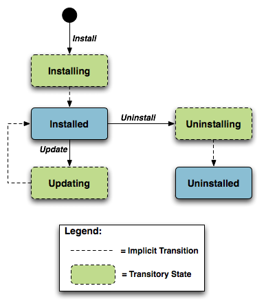
This state machine shows 5 individual states (3 of which are transitory) and 3 explicitly triggered state transitions.
The explicit transitions among the non-transitory states are
triggered by the USP commands: InstallDU(),
Update() and Uninstall() or triggered via
means other than the USP commands (e.g. user-triggered or
device-triggered).
The explicit transitions include:
1 - Install, which initiates the process of Installing a DU. The device might need to transfer a file from the location indicated by a URL in the method call. Once the resources are available on the device, the device begins the installation process:
In the Installing state, the DU is in the process of being Installed and will transition to that state unless prevented by a fault. Note that the Controller has the option to choose which EE to install a particular DU to, although it can also leave that choice up to the device. If the Controller does specify the EE, it is up to the Controller to specify one that is compatible with the DU it is attempting to Install (e.g., Docker for an OCI image).
In the Installed state, the DU has been successfully downloaded and installed on the relevant EE. At this point it might or might not be Resolved. If it is Resolved, the associated EUs can be started; otherwise an attempt to start the associated EUs will result in a failure. How dependencies are resolved is implementation and EE dependent.
R-SMM.0 - An installed DU MUST persist across reboots. The DU persists until it is Uninstalled.
2 - Update, which initiates a process to update a previously existing
DU. As with Install, the device might need to transfer a file from the
location indicated by a URL in the respective command. If no URL is
provided in the command, the device uses the last URL stored in the
DeploymentUnit table (including any related authentication
credentials) used from either Install or a previous Update. Once the
resources are available on the device, the device begins the updating
process:
In the Updating state, the DU is in the process of being Updated and will transition to the Installed state. As with initial installation, the DU might or might not have dependencies resolved at this time.
During the Updating state, the associated EUs that had been in the Active state transition to Idle during the duration of the Update. They are automatically restarted once the Update process is complete.
3 - Uninstall, which initiates the process of uninstalling the DU and removing the resources from the device. It is possible that a DU to be Uninstalled could have been providing shared dependencies to another DU; it is possible therefore that the state of other DUs and/or EUs could be affected by the DU being Uninstalled.
In the Uninstalling state, the DU is in the process of being Uninstalled and will transition to that state unless prevented by a fault.
In the Uninstalled state, the DU is no longer available as a resource on the device. Garbage clean up of the actual resources are EE and implementation dependent. In many cases, the resource(s) will be removed automatically at the time of un-installation. The removal of any associated EUs is part of DU clean up.
R-SMM.1 - The device MUST
complete the requested operation within 24 hours of responding to the
InstallDU(), Update() or
Uninstall() command. If the device has not been able to
complete the operation request within that 24 hour time window, it MUST
consider the operation in error and send the appropriate Error Message
to the operation in the DUStateChange! event. If a DU state
change fails, the device MUST NOT attempt to retry the state change on
its own initiative, but instead MUST report the failure of the command
in the DUStateChange! event.
The inventory of available DUs along with their current state can be
found in the SoftwareModules service element found in the
Root data model, i.e., the
SoftwareModules.DeploymentUnit.{i}. Object. This Object
contains a list of all the DUs currently on the device, along with
pertinent information such as DU identifiers, current state, whether the
DU is Resolved, information about the DU itself such as vendor and
version, the list of associated EUs, and the EEs on which the particular
DU is installed.
DUs have a number of identifiers, each contributed by a different actor in the ecosystem:
A Universally Unique Identifier (UUID) either assigned by the Controller or generated by the device at the time of Installation. This identifier gives the management server a means to uniquely identify a particular DU across the population of devices on which it is installed. A DU will, therefore, have the same UUID on different devices, but there can be no more than one DU with the same UUID and version installed to an EE on a particular device. See UUID Generation below for more information.
A Deployment Unit Identifier (DUID) assigned by the EE on which it is deployed; this identifier is specific to the particular EE, and different EEs might have different logic for the assigning of this value. A Name assigned by the author of the DU.
The creation of a particular DU instance in the data model occurs during the Installation process. It is at this time that the DUID is assigned by the EE. Upon Uninstall, the data model instance will be removed from the DU table once the resource itself has been removed from the device. Since garbage clean up is EE and implementation dependent, it is therefore possible that a particular DU might never appear in the data model in the Uninstalled state but rather disappear at the time of the state transition. It is also possible that an event, such as a reboot, could be necessary before the associated resources are removed.
I.2.1.1 UUID Generation
An important aspect of the UUID is that it might be generated by either the Controller and provided to the device as part of the Install command, or generated by the device either if the Controller does not provide a UUID in the Install command or if the DU is Installed outside USP-based management, such as at the factory or via a LAN-side mechanism (e.g. UPnP DM). Because the UUID is meant to uniquely identify a DU across a population of devices, it is important that the UUID be the same whether generated by the Controller or the device. In order to ensure this, the UUID is generated (whether by Controller or device) according to the rules defined by RFC 4122 [16] Version 5 (Name-Based) and the Device:2 Data Model [3]. The following are some possible scenarios:
The DU is Installed via USP with a Controller generated UUID and is subsequently Updated/Uninstalled via USP. All post-Install management actions require the UUID to address the DU, which is retained across version changes.
The DU is factory Installed with a device generated UUID and is subsequently Updated/Uninstalled via USP. In this case the Controller can either choose to generate this UUID if it has access to the information necessary to create it or to learn the UUID by interrogating the data model.
The DU is Installed via USP with a Controller generated UUID and is subsequently Updated/Uninstalled via a LAN-side mechanism. In this scenario it is possible that the LAN-side mechanism is unaware of the UUID and uses its own protocol-specific mechanism to identify and address the DU. The UUID, however, is still retained across version changes. If
DUStateChange!events are subscribed to by the Controller for the device, the device also sends that event (containing the UUID) to the subscribed Controllers once the LAN-side triggered state change has completed.The DU is Installed via USP but the Controller provides no UUID in the
InstallDU()command. In this case the device generates the UUID, which must be used by the Controller in any future USP-based Updates or Uninstalls. Depending on its implementation, the Controller might choose to generate the UUID at the time of the future operations, learn the value of the UUID from theDUStateChange!event for theInstallDU(),Update()orUninstall()command, or learn it by interrogating the data model.
The DU is Installed via a LAN-side mechanism and is subsequently
Updated/Uninstalled via USP. Since it is likely that the LAN-side
mechanism does not provide a Version 5 Name-Based UUID in its
protocol-specific Install operation, it is expected that the device
generates the UUID in this case when it creates the DU instance in the
data model. Depending on its implementation, the Controller might choose
to generate the UUID for later operations if it has access to the
information necessary to create it, learn the UUID from the
DUStateChange! event, if subscribed, or learn it by
interrogating the instantiated data model.
I.2.2 Execution Units
Below is the state machine diagram2 for the lifecycle of EUs.
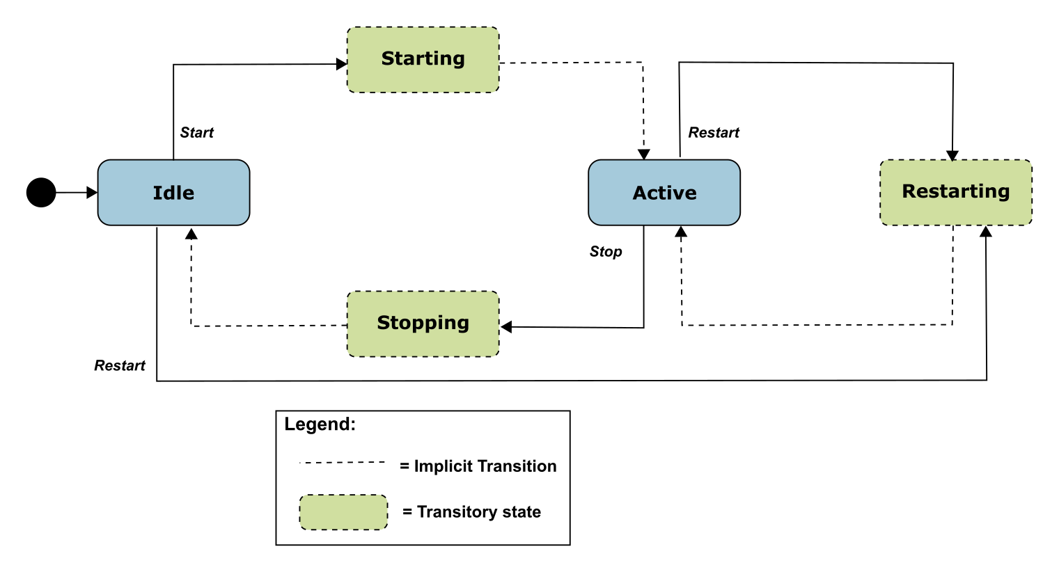
This state machine shows 5 states (3 of them transitory) and four explicitly triggered state transitions.
The state transitions between the non-transitory states are triggered
by executing the
SoftwareModules.ExecutionUnit.{i}.SetRequestedState() or
the SoftwareModules.ExecutionUnit.{i}.Restart() command.
The explicit transitions are as follows:
In order to Start an EU, the Controller sends a
SetRequestedState()command with theRequestedStateParameter set to Active. The EU enters the Starting state, during which it takes any necessary steps to move to the Active state, and it will transition to that state unless prevented by a fault. Note that an EU can only be successfully started if the DU with which it is associated has all dependencies Resolved. If this is not the case, then the EU’s status remains as Idle, and theExecutionFaultCodeandExecutionFaultMessageParameters are updated appropriately.In order to Stop an EU, the Controller sends a
SetRequestedState()command with theRequestedStateParameter set to Idle. The EU enters the Stopping state, during which it takes any necessary steps to move to the Idle state, and then transitions to that state.In order to Restart an EU, the Controller sends a
Restart()command. The EU enters the Restarting state, during which it stops execution and then re-starts before transitioning back to the Active state. The command may be rejected with error code 7230 (Invalid Execution Environment State) if the EU is currently in a state of Stopping.It is also possible that the EU could transition to the Active, Restarting, or Idle state without being explicitly instructed to do so by a Controller (e.g., if the EU is allowed to AutoStart, in combination with the run level mechanism, or if an AutoRestart mechanism is enabled, or if operation of the EU is disrupted because of a later dependency error). A Controller can be notified of these autonomous state changes by creating a
Subscription.{i}.Object Instance for aValueChangenotification type that references theSoftwareModules.ExecutionUnit.{i}.StatusParameter.
The inventory of available EUs along with their current state can be
found in the SoftwareModules service element found in the
Root data model; i.e., the
SoftwareModules.ExecutionUnit.{i}. Object. This Object
contains a list of all the EUs currently on the device along with
accompanying status and any current errors as well as resource
utilization related to the EU, including memory and disk space in
use.
EUs have a number of identifiers, each contributed by a different actor in the ecosystem:
An Execution Unit Identifier (EUID) assigned by the EE on which it is deployed; this identifier is specific to the particular EE, and different EEs might have different logic for assigning this value. There can be only one EU with a particular EUID.
A Name provided by the developer and specific to the associated DU.
A Label assigned by the EE; this is a locally defined name for the EU.
The creation of a particular EU instance in the data model occurs during the Installation process of the associated DU. It is at this time that the EUID is assigned by the EE as well. The configuration exposed by a particular EU is available from the time the EU is created in the data model, whether or not the EU is Active. Upon Uninstall of the associated DU, it is expected that the EU would transition to the Idle State, and the data model instance would be removed from the EU table once the associated resources had been removed from the device. Garbage clean up, however, is EE and implementation dependent.
Although the majority of EUs represent resources such as scripts that
can be started or stopped, there are some inert resources, such as
libraries, which are represented as EUs. In this case, these EUs behave
with respect to the management interface as a “regular” EU. In other
words, they respond successfully to Stop and Start commands, even though
they have no operational meaning and update the
SoftwareModules.ExecutionUnit.{i}.Status Parameter
accordingly. In most cases the Status would not be expected
to transition to another state on its own, except in cases where its
associated DU is Updated or Uninstalled or its associated EE is Enabled
or Disabled, in which cases the library EU acts as any other EU.
Restarting such an EU will result in a successful response but the state
remains unchanged.
The EUs created by the Installation of a particular DU might provide functionality to the device that requires configuration by a Controller. This configuration could be exposed via the USP data model in five ways:
Service data model (if, for example, the EU provides VoIP functionality, configuration would be exposed via the Voice Service data model defined in TR-104).
Standard Objects and parameters in the device’s root data model (if, for example, the EU provides port mapping capability, the configuration would be exposed via the port mapping table defined in the Device:2 Data Model [3]).
Instances of standard Objects in the Root or any Service data model, (if, for example, the EU provides support for an additional Codec in a VoIP service).
Vendor extension Objects and Parameters that enhance and extend the capabilities of standard Objects (if, for example, the EU provides enhanced UserInterface capabilities)
Standalone vendor extension Objects that are directly controlled Objects of the EU (for example, a new vendor specific Object providing configuration for a movies on demand service).
In all cases the GetSupportedDM and GetInstances Messages can be used to retrieve the associated supported data model along with the corresponding Object Instances.
All data model services, Objects, and Parameters related to a
particular EU come into existence at the time of Installation or Update
of the related DU, The related data model disappears from the device’s
data model tree at the time of Uninstall and clean up of the related DU
resources. It is possible that the device could encounter errors during
the process of discovering and creating EUs; if this happens, it is not
expected that the device would roll back any data model it has created
up until this point but would rather set the
ExecutionFaultCode of the EU to “Unstartable.”
In this case, it is not expected that any faults (with the exception of
System Resources Exceeded) would have been generated in response to the
Install or Update operation. See below for more information on EU
faults.
The configuration of EUs could be backed up and restored using vendor configuration files. The EU Object in the data model contains a Parameter, which is a path reference to an instance in the vendor config file table in the Root data model. This path reference indicates the vendor config file associated with the configuration of the particular EU from which the associated Object Instance could be backed up or restored using respective commands for that Object Instance.
It is also possible that applications could have dedicated log files. The EU Object also contains a Parameter, which is a path reference to an instance in the log file table in the root data model. This path reference indicates the log file associated with a particular EU from which the referenced Object Instance could be retrieved using the Upload command for that Object Instance.
I.3 Execution Environment Concepts
As discussed above, an EE is a software platform that supports the dynamic loading and unloading of modules. A given device can have multiple EEs of various types and these EEs can be layered on top of each other. The following diagram gives a possible implementation of multiple EEs.
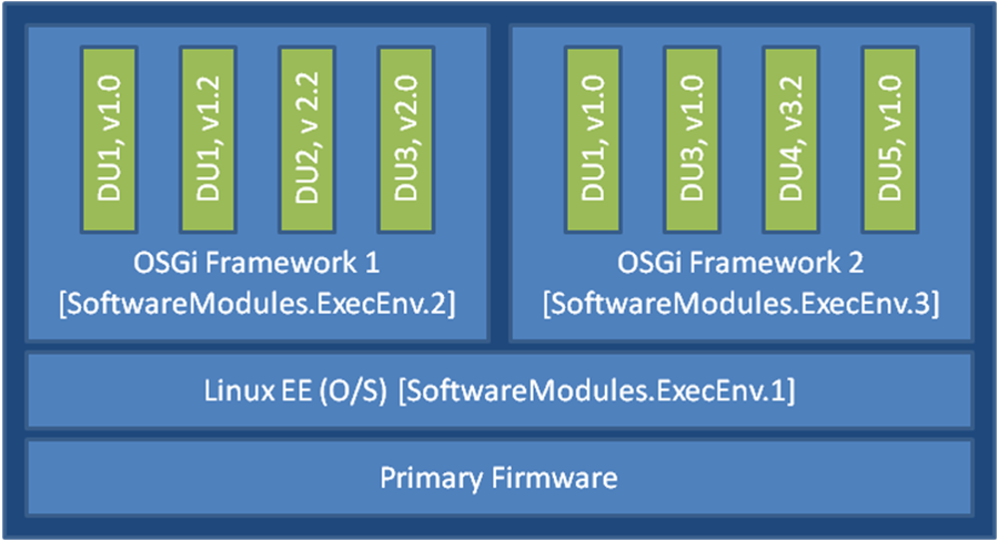
In this example, the device exposes its Linux Operating System as an
EE and has two different OSGi frameworks layered on top of it, all of
which are modeled as separate ExecEnv Object Instances. In order to
indicate the layering to a Controller, the two OSGi framework Objects
(.ExecEnv.2 and .ExecEnv.3) would populate the
Exec.Env.{i}.Parent Parameter with a path reference to the
Linux Object (.ExecEnv.1). The Linux EE Object would
populate that Parameter with an empty string to indicate that it is not
layered on top of any managed EE.
Note that the above is merely an example; whether a device supports multiple frameworks of the same type and whether it exposes its Operating System as an Execution Environment for the purposes of management is implementation specific.
Multiple versions of a DU can be installed within a single EE
instance, but there can only be one instance of a given version at a
time. In the above diagram, there are two versions of DU1, v1.0 and v1.2
installed on .ExecEnv.2. If an attempt is made to update
DU1 to version 1.2, or to install another DU with version 1.0 or 1.2, on
ExecEnv.2, the operation will fail.
A DU can also be installed to multiple EEs. In the above example, DU1
is installed both to ExecEnv.2and ExecEnv.3.
The Installation is accomplished by sending two separate
InstallDU() commands where one command’s
ExecEnvRef Parameter has a value of
“.ExecEnv.2” and the other command’s
ExecEnvRef Parameter as a value of “.ExecEnv.3” ; note that
the USP Controller is required to handle cases where there is an
expectation that the installation of both deployment units is
atomic.
When DUs are Updated, the DU instances on all EEs are affected. For
example, in the above diagram, if DU1 v.1.0 is updated to version 2.0,
the instances on both .ExecEnv.2 and
.ExecEnv.3 will update to version 2.0.
For Uninstall, a Controller can either indicate the specific EE from which the DU should be removed, or not indicate a specific EE, in which case the DU is removed from all EEs.
An EE can be enabled and disabled by a Controller. Sending a
SoftwareModules.ExecEnv.{i}.Restart() command is equivalent
to first disabling and then later enabling the EE, but also allows the
reason for and the time of the restart to be recorded in
SoftwareModules.ExecEnc.{i}.RestartReason and
SoftwareModules.ExecEnc.{i}.LastRestarted respectively.
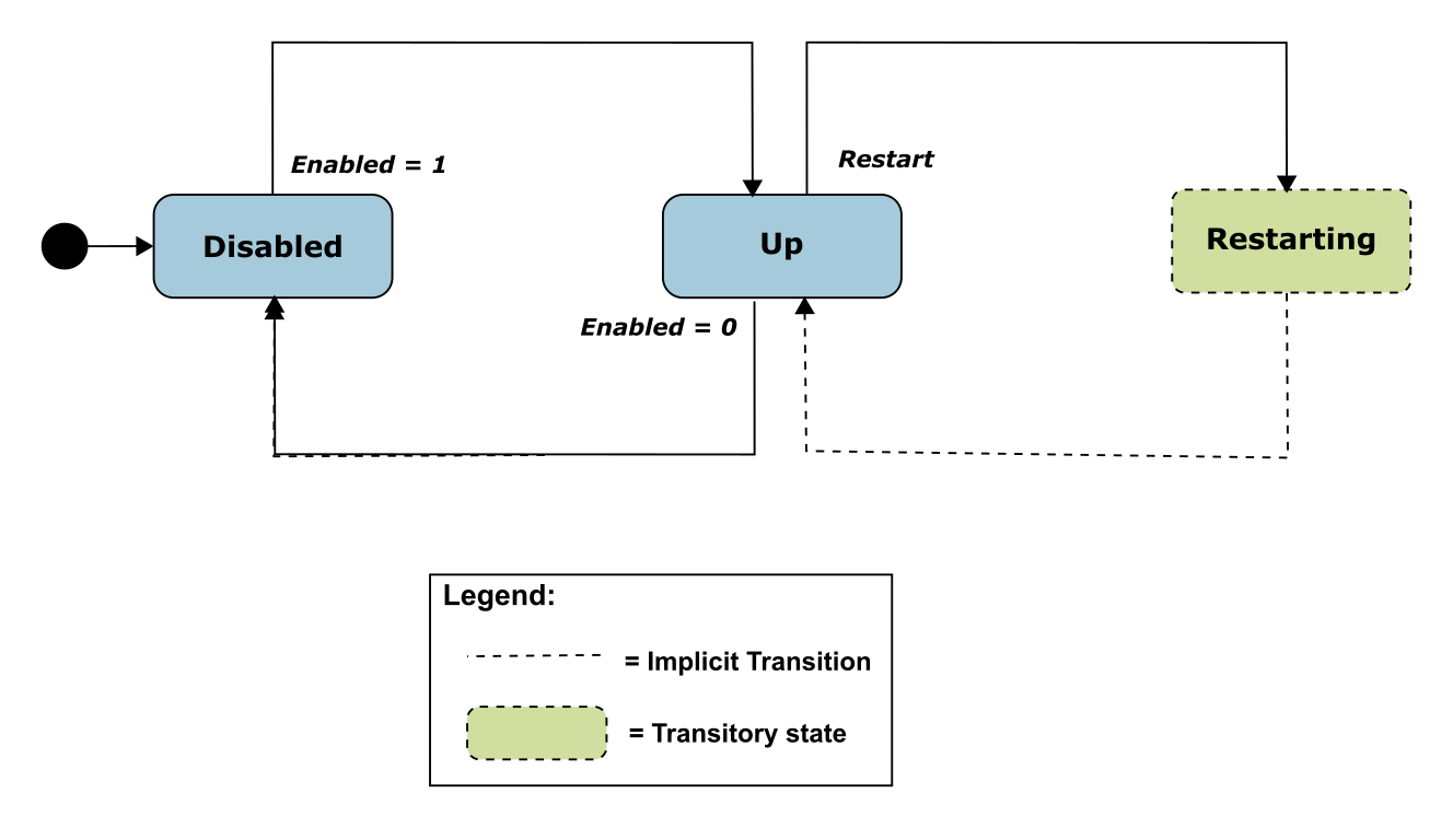
When an EE instance is disabled by a Controller, the EE itself shuts
down. Additionally, any EUs associated with the EE automatically
transition to Stopped and the ExecutionFaultCode Parameter
value is Unstartable. The state of the associated DUs
remains the same. If a USP command that changes the DU state is
attempted on any of the DUs associated with a disabled EE, the operation
fails and an “Invalid value” error is returned in the
DUStateChange! event for the affected DU instance. It
should be noted if the Operating System of the device is exposed as an
EE, disabling it could result in the device being put into a
non-operational and non-manageable state. It should also be noted that
disabling the EE on which the USP Agent resides can result in the device
becoming unmanageable via USP.
I.3.1 Managing Execution Environments
An implementation may provide for Execution Environments to be added
or removed at run-time. These implementations should provide the
SoftwareModules.ExecEnvClass table and its associated
AddExecEnv() command. For example in Figure 29 the
ExecEnvClassRef of the Linux EE would point to one entry in
SoftwareModules.ExecEnvClass while the two OSGI Frameworks
would point to to another entry. A new OSGI Framework instance could be
created using
SoftwareModules.ExecEnvClass.{i}.AddExecEnv(), or an
instance could be removed using
SoftwareModules.ExecEnv.{i}.Remove().
The ExecEnvClass.{i}.Capability table describes the
class of EE in terms of the kinds of DUs it supports. For example a web
services framework would probably support the installation of WAR files,
but it may also support OSGi Bundles as a DU format.
(Note: In the example shown in Figure 29 the ExecEnvClassRef of the
Linux EE could also be left blank, as apparently this EE does not
support the installation of any kind of DU nor is it possible to add new
instances.)
I.3.2 Application Data Volumes
An Execution Environment may offer filesystem storage facilities to
the software modules which are installed into it; these EEs should
provide the SoftwareModules.ExecEnv.{i}.ApplicationData
table which exposes the storage volumes which currently exist.
Each application data volume is associated with an
“application” and a volume Name (so that an application may
own multiple volumes). The application is identified by the UUID of its
DU, and hence by the Vendor and Name of a Deployment Unit. This makes it
possible for a data volume to persist across an Update of the DU or even
across an Uninstall and subsequent re-Install, if desired. At the
opposite extreme, an application data volume may be marked
“Retain Until Stopped”, meaning that the data will be lost
when application no longer has any Active EUs (conceptually these
volumes are destroyed, and will be re-created when an EU becomes
Active).
The set of application data volumes needed by an application are
specified in an optional parameter of the InstallDU()
command, and can be modified by the Update() command. Note
that the parameter specifies the retention policy for each volume, but
not where it is stored - a volume might be stored on the local flash of
one device while another device would store the same volume in the
cloud. This makes it easier to design applications which can be deployed
across a wide range of devices without needing to know the detailed
storage layout of each device.
By default the Update() and Uninstall()
commands cause all application data volumes associated with the affected
DUs to be lost. This can be prevented by setting the optional
RetainData argument to true; in the case of
Uninstall() this will result in an “orphaned”
volume with an ApplicationUUID which does not match any DU
installed in the EE. The
SoftwareModules.ExecEnv.{i}.ApplicationData.{i}.Remove()
command is available to clean up orphaned data volumes if they are no
longer needed. Implementations are advised to reject any attempt to
invoke this command on a data volume with an
ApplicationUUID which matches that of a DU which is
currently installed in the EE, with error code 7229 (Invalid Deployment
Unit State).
I.3.3 Signing Deployment Units
An Execution Environment may require any DU which is Installed into it to be signed by an authorized principal. A signature may take many forms, such as a JSON Web Signature (JWS, RFC 7515) or GNU Privacy Guard (GPG, RFC 4880); however in essence it always amounts to a cryptographically-signed statement that a certain artifact is authentic. Typically the document is identified by a hash of its contents (so the signature also provides assurance of integrity), and asymmetric encryption is used so that both the signature itself and the public key which can be used to verify its authenticity can be transmitted over an insecure channel without risk of compromise.
It may be possible to derive the URL of the signature from the URL of
the DU itself, for example by appending a suffix such as “.sig”.
Alternatively an optional Signature argument can be
included in the Install or Update command,
providing greater operational flexibility.
If the public key(s) which are used to verify signatures are
distributed in the form of X.509 certificates, these may be stored in
the Device.Security.Certificate table. the Execution
Environment may then list the relevant entries in its
Signers parameter.
I.4 Fault Model
Faults can occur at a number of steps in the software module process. The following sections discuss Deployment Unit faults and Execution Unit faults.
I.4.1 DU Faults
There are two basic types of DU faults: Operation failures and USP
message errors that are the result of the invoking the
InstallDU(),Update(),UninstallDU(),
Reset(), SetRunLevel() and
SetRequestedState() commands.
I.4.1.1 Install Faults
Most Install faults will be recognized before resources or instances are created on the device. When there is an Operation failure at Install, there are no resources installed on the device and no DU (or EU) instances are created in the data model. Similarly, if there are any command failures, besides System Resources Exceeded, there are no resources installed on the device and no DU (or EU) instances created in the data model.
There are a number of command failures defined for Installation. The
first category is those faults associated with the file server or
attempt to transfer the DU resource and are the same as those defined
for the existing InstallDU() and Update()
commands. These include:
- Userinfo element being specified in the URL
- The URL being unavailable (either because the host cannot be reached or because the resource is unavailable)
- Authentication failures due to incorrectly supplied credentials
- The URL transport method specified not being supported by the device or server
- The file transfer being interrupted (because of a device reboot or loss of connectivity, for example)
The second category of faults relate to issues with the DU and the Execution Environment. These are specific to Software Module Management and include:
- The EE reference specified by a Controller in the
InstallDU()command does not exist in the data model. Note that the Controller can simply omit the EE reference in the request and allow the deice to choose the destination. - The EE being disabled. This fault can occur when the
InstallDU()command explicitly specifies a disabled EE. If there is no EE specified in the request, this fault could occur because the only possible destination EE for the DU (the only OSGi framework instance in the case of an OSGi bundle, for example) is disabled. The device is expected to make every attempt not to use a disabled EE in this scenario, however. - Any mismatch existing between the DU and the EE (attempting to install a Linux package on an OSGi framework instance, for example). This fault can occur when the request explicitly specifies a mismatching EE. If there is no EE specified in the request, this fault could occur when there is no EE at all on the device that can support the DU.
- A DU of the same version already existing on the EE.
Finally there are a number of faults related to the DU resource itself. These include:
- The UUID in the request not matching the format specified in RFC 4122 [16] Version 5 (Name-based).
- A corrupted DU resource, or the DU not being installable for other reasons, such as not being signed by any trusted entity
- The installation of the DU requiring more system resources, such as disk space, memory, etc., than the device has available. Note that this error is not to be used to indicate that more operations have been requested than the device can support, which is indicated by the Resourced Exceeded error (described above).
I.4.1.2 Update Faults
When there is a fault on an Update of a DU of any kind, the DU
remains at the version it was before the attempted DU state change, and
it also remains in the Installed state (i.e., it is not Uninstalled). If
for any reason the a Controller wishes to remove a DU after an
unsuccessful Update, it must do so manually using an
Uninstall() command. When there is a USP message error for
the Update, there are no new resources installed on the device and no DU
(or EU) instances are changed in the data model. Similarly, if there are
any Operation failures, besides System Resources Exceeded, there are no
new resources installed on the device and no DU (or EU) instances are
changed in the data model. The state of any associated EUs or any
dependent EUs in the event of an Update failure is EE and implementation
dependent.
There are a number of Operation failures defined for Update of a DU.
The first category is those faults associated with the file server or
attempt to transfer the DU resource and are the same as those defined
for the existing Update() command. These include:
- Userinfo element being specified in the URL
- The URL being unavailable (either because the host cannot be reached or because the resource is unavailable)
- Authentication failures due to incorrectly supplied credentials
- The URL transport method specified not being supported by the device or server
- The file transfer being interrupted (because of a device reboot or loss of connectivity, for example)
The second category of faults relate to issues with the DU and the Execution Environment. These are specific to Software Module Management and include:
- The EE on which the targeted DU resides being disabled. This fault can occur when the request explicitly specifies the UUID of a DU on a disabled EE or when the request explicitly specifies a URL last used by a DU on a disabled EE. If neither the URL nor UUID was specified in the request, this fault can occur when at least one DU resides on a disabled EE.
- Any mismatch existing between the DU and the EE. This fault occurs when the content of the updated DU does not match the EE on which it resides (for example, an attempt is made to Update a Linux package with a DU that is an OSGi bundle).
- Updating the DU would cause it to have the same version as a DU already installed on the EE.
- The version of the DU not being specified in the request when there are multiple versions installed on the EE.
Finally there are a number of faults related to the DU resource itself. These include:
- The UUID in the request not matching the format specified in RFC 4122 [16] Version 5 (Name-Based).
- A corrupted DU resource, or the DU not being installable for other reasons, such as not being signed by any trusted entity
- The DU cannot be found in the data model. This fault can occur when the request explicitly specifies the UUID (or combination of UUID and version) of a DU that is unknown. It can also occur when the request does not specify a UUID but explicitly specifies a URL that has never been used to previously Install or Update a DU.
- Attempting to downgrade the DU version.
- Attempting to Update a DU not in the Installed state.
- Updating the DU requiring more system resources, such as disk space, memory, etc., than the device has available. Note that this error is not to be used to indicate that more operations have been requested than the device can support, which is indicated by the Resourced Exceeded USP error (described above).
I.4.1.3 Uninstall Faults
When there is a fault due to the Uninstall of a DU fault of any kind, the DU does not transition to the Uninstalled state and no resources are removed from the device. No changes are made to the EU-related portions of the data model (including the EU Objects themselves and the related Objects and Parameters that came into existence because of this DU).
There are Operation failures defined for Uninstall of a DU. They are as follows:
- The EE on which the targeted DU resides is disabled. Note that if the Uninstall operation targets DUs across multiple EEs, this fault will occur if at least one of the EEs on which the DU resides is disabled.
- The DU cannot be found in the data model. If the EE is specified in the request, this error occurs when there is no UUID (or UUID and version) matching the one requested for the specified EE. If there is no EE specified in the request, this error occurs when there is no UUID matching the one in the requested on any EE in the data model, or, if the version is also specified in the request, then this error occurs when there is no DU with this combination of UUID and version on any EE in the data model.
- The UUID in the request not matching the format specified in RFC 4122 [16] Version 5 (Name- Based).
- The DU caused an EE to come into existence on which at least 1 DU is Installed.
I.4.2 EU Faults
EU state transitions are triggered by the
SetRequestedState() command. One type of EU fault is a USP
Error Message sent in response to USP operate Message for the
SetRequestedState() command. The USP Error Message defined
are therefore simply a subset of the errors defined for the generic USP
Operate Message (e.g., Request Denied, Internal Error).
Note that there is one case specific to Software Module Management:
if a Controller tries to Start an EU on a disabled EE using the
SetRequestedState() command, the device returns a
“7012 Invalid Value” error response to the command
request.
There are also Software Module Management specific faults indicated
in the ExecutionFaultCode and
ExecutionFaultMessage Parameters in the data model. In
addition to providing software module specific fault information, this
Parameter is especially important in a number of scenarios:
- Errors that occur at a later date than the original USP Message, such as a Dependency Failure that occurs several days after successful Start of an EU because a DU providing dependencies is later Uninstalled.
- State transition errors that are triggered by the Autostart/Run level mechanism.
- “Autonomous” state transitions triggered outside the purview of USP, such as by a LAN-side protocol.
The faults in the ExecutionFaultCode Parameter are
defined as follows:
FailureOnStart– the EU failed to start despite being requested to do so by the Controller.FailureOnAutoStart– the EU failed to start when enabled to do so automatically.FailureOnStop– the EU failed to stop despite being requested to do so by the Controller.FailureWhileActive– an EU that had previously successfully been started either via an explicit transition or automatically later fails.DependencyFailure– this is a more specific fault scenario in which the EU is unable to start or stops at a later date because of unresolved dependenciesUnstartable– some error with the EU resource, its configuration, or the state of the associated DU or EE, such as the EE being disabled, prevents it from being started.
When the EU is not currently in fault, this Parameter returns the
value NoFault. The ExecutionFaultMessage
Parameter provides additional, implementation specific information about
the fault in question. The ExecutionFaultCode and
ExecutionFaultMessage Parameters are triggered Parameters.
In other words, it is not expected that an Controller could read this
Parameter before issuing a USP Message and see that there was a
Dependency Failure that it would attempt to resolve first. If a
Controller wants a notification when these Parameters change, the
Controller can subscribe to the ValueChange notification type with the
Parameters for the referenced EU.
Appendix II: Firmware Management of Devices with USP Agents
Many manufacturers build and deploy devices that are able to support multiple firmware images (i.e. multiple firmware images can be installed on an Agent at the same time). There are at least a couple of advantages to this strategy:
Having multiple firmware images installed improves the robustness and stability of the device because, in all likelihood, one of the installed images will be stable and bootable. Should a device not be able to boot a newly installed firmware image, it could have the ability to attempt to boot from a different firmware image, thus allowing the device to come back online.
Support for multiple firmware images offers the ability for the service provider to have a new firmware downloaded (but not activated) to the device at any point during the day, then perhaps requiring only a Set Message and an Operate Message to invoke the Reboot command at some later time (perhaps during a short maintenance window or when the device is idle) to cause the device to switch over to the new firmware. Along with reducing the impact on the subscriber, the ability to spread the download portion a firmware upgrade over a longer period of time (eg, the entire day or over several days) can help minimize the impact of the upgrade on the provider’s network.
This Appendix discusses how to utilize the firmware image table on a device to support firmware upgrades whether the device supports multiple instances or just a single instance.
II.1 Getting the firmware image onto the device
A Controller can download a firmware image to an Agent by invoking
the Download() command (via the Operate Message) found
within an instance of the
Device.DeviceInfo.FirmwareImage.{i}. data model table. The
Download() command will cause the referenced file to be
downloaded into the firmware image instance being operated on, and it
will cause that file to be validated by the Agent (the validation
process would include any normal system validate of a firmware image as
well as the check sum validation provided in the Download()
command).
If an Agent only supports a single firmware image instance then a
Controller would invoke the Download() command on that
active firmware image instance using the AutoActivate
argument to immediately activate the new firmware after it has been
downloaded. Neither the Device.DeviceInfo.BootFirmwareImage
Parameter nor the
Device.DeviceInfo.FirmwareImage.{i}.Activate() command
would typically be implemented by a device that only supports a single
firmware image instance.
If an Agent supports more than a single firmware image instance then
a Controller would typically invoke the Download() command
on a non-active firmware image instance in an effort of preserving the
current firmware image in case of an error while upgrading the firmware.
A firmware image instance is considered active if it is the currently
running firmware image.
II.2 Using multiple firmware images
This section discusses the added functionality available when a
device supports two or more instances in the
Device.DeviceInfo.FirmwareImage.{i}. data model table.
II.2.1 Switching firmware images
Once a device has multiple firmware images downloaded, validated, and available, a Controller can use the data model to query what images are on the device, which image is active, and configure which image to activate.
A Controller can activate a new firmware image by following one of
two different procedures: (A) the Controller can modify the
Device.DeviceInfo.BootFirmwareImage Parameter to point to
the Device.DeviceInfo.FirmwareImage.{i}. Object Instance
that contains the desired firmware image and then reboot the device by
invoking an Operate Message with a Reboot()
command or (B) the Controller can invoke an Operate Message with an
Activate() command against the desired
FirmwareImage instance.
When attempting to get a device to switch to a different firmware
image, it is recommended that the Controller either subscribe to a
ValueChange notification on the
DeviceInfo.SoftwareVersion Parameter or subscribe to the
Boot! Event notification. If the Software Version value has
not changed or the Boot! Event’s
FirmwareUpdated argument is false, it could be an
indication that the device had problems booting the target firmware
image.
II.2.2 Performing a delayed firmware upgrade
One of the benefits to having support for multiple firmware images on a device is that it provides an opportunity to push a firmware image to a device and then have the device switch to that image at a later time. This functionally allows a service provider to push a firmware image to a set of devices at any point during the day and then use a maintenance window to switch all of the target devices to the target firmware.
This ability is of value because normally the download of the firmware and the switch to the new image would both have to take place during the maintenance window. Bandwidth limitations may have an impact on the number of devices that can be performing the download at the same time. If this is the case, the number of devices that can be upgrading at the same time may be lower than desired, requiring multiple maintenance windows to complete the upgrade. However, support for multiple firmware images allows for the service provider to push firmware images over a longer period of time and then use a smaller maintenance window to tell the device to switch firmware images. This can result is shorter system-wide firmware upgrades.
II.2.3 Recovering from a failed upgrade
Another benefit of having multiple firmware images on a device is that if a device cannot boot into a target firmware image because of some problem with the image, the device could then try to boot one of the other firmware images.
When there are two images, the device would simply try booting the alternate image (which, ideally, holds the previous version of the firmware). If there are more than two images, the device could try booting from any of the other available images. Ideally, the device would keep track of and try to boot from the previously known working firmware (assuming that firmware is still installed on the device).
If the activation of a firmware image causes the device to lose its
USP Agent connectivity to the controller for any reason (i.e., the USP
Agent fails to send messages to the Controller, or the messages are not
understood by the Controller), the device is expected to roll back to
the previously activated image and add appropriate information to the
Device.DeviceInfo.FirmwareImage.{i}.BootFailureLog
parameter of the failed image.
Should the device boot a firmware image other than that specified via
the Device.DeviceInfo.BootFirmwareImage Parameter, it is
important that the device not change the value of the
Device.DeviceInfo.BootFirmwareImage Parameter to point to
the currently-running firmware image Object. If the device was to change
this Parameter value, it could make troubleshooting problems with a
firmware image switch more difficult.
It was recommended above that the Controller keep track of the value
of Device.DeviceInfo.SoftwareVersion Parameter or the
FirmwareUpdated flag in the Boot! event. If
the version changes unexpectedly or the FirmwareUpdated
flag is set to true, it could be an indication that the
device had problems booting a particular firmware image.
Appendix III: Device Proxy
This appendix describes a Theory of Operations for the
Device.ProxiedDevice. Object defined in the Device:2 Data
Model [3].
The Device.ProxiedDevice table is defined as:
“Each entry in the table is a ProxiedDevice Object that is a mount point. Each ProxiedDevice represents distinct hardware Devices. ProxiedDevice Objects are virtual and abstracted representation of functionality that exists on hardware other than that which the Agent is running.”
An implementation of the Device.ProxiedDevice. Object
may be used in an IoT Gateway that proxies devices that are connected to
it via technologies other than USP such as Z-Wave, ZigBee, Wi-Fi, etc.
By designating a table of ProxiedDevice Objects, each
defined as a mount point, this allows a data model with Objects that are
mountable to be used to represent the capabilities of each of the
ProxiedDevice table instances.
For example, if Device.WiFi. and
Device.TemperatureStatus. Objects are modeled by the Agent,
then Device.ProxiedDevice.1.WiFi.Radio.1. models a
distinctly separate hardware device and has no relationship with
Device.WiFi.Radio.1.. The ProxiedDevice
Objects may each represent entirely different types of devices each with
a different set of Objects. The
ProxiedDevice.1.TemperatureStatus.TemperatureSensor.1.
Object has no physical relationship to
ProxiedDevice.2.TemperatureStatus.TemperatureSensor.1. as
they represent temperature sensors that exist on separate hardware. The
mount point allows Device.ProxiedDevice.1.WiFi.Radio. and
Device.ProxiedDevice.1.TemperatureStatus.TemperatureSensor.
to represent the full set of capabilities for the device being proxied.
This provides a Controller a distinct path to each
ProxiedDevice Object.
Appendix IV: Communications Proxying
This appendix describes a variety of proxies that can be created and deployed in order to enhance the USP experience.
The types of proxies described are:
- Discovery Proxy: proxies discovery and advertisement; does not proxy USP messages
- Connectivity Proxy: proxies USP messages at the IP layer; does not care about MTP or USP message headers or content; may do message caching for sleeping devices
- MTP Proxy: proxies USP messages at the MTP layer and below; does not care about USP Message headers or content; may do message caching for sleeping devices [Note: The MTP Proxy may choose to look at the USP Record to get information related to USP Endpoints, especially when proxying WebSocket MTP.]
- USP to Non-USP Proxy: Proxies between USP and a non-USP management or control protocol
IV.1 Proxying Building Block Functions
These proxies are comprised of one or more of the building block functions described in Table 1.
| Function | Description |
|---|---|
| L3/4 Translation Function | Translates up to and including the IP and transport layer (e.g., UDP, TCP) protocol headers, while leaving all higher layer protocol headers and payloads untouched. |
| MTP Translation Function | Translates up to and including the Message Transfer Protocol (MTP) header, while leaving the USP Record untouched. Requires knowledge of how to bind USP to two or more MTPs. |
| USP to non-USP Translation Function | Translates all headers and the USP Record and USP Message into data model and headers of another management protocol. Requires proxy to have an Agent. |
| Caching Function | Can hold on to USP Messages intended for Endpoints that are intermittently connected, until a time when that Endpoint is connected. The USP Message is not altered, so no Endpoint is required to be aware of the existence of this function. |
| Non-USP Advertisement Function | Responds to discovery queries using protocols other than USP (e.g., DNS-SD, DNS, DHCP) on behalf of Endpoints. May include a DNS Server. See Discovery section for formatting of various non-USP discovery protocols in the context of USP. |
| Non-USP Discovery Function | Discovers Endpoints through discovery queries using protocols other than USP. See Discovery section for formatting of various non-USP discovery protocols in the context of USP. |
| Agent USP Advertisement Function | Maintains a USP data model table of discovered Agents. Requires an Agent. |
IV.2 Discovery Proxy
A Discovery Proxy simply repeats the exact information that it discovers from Endpoints. This is particularly useful in a multi-segment LAN, where mDNS messages do not cross segment boundaries. The DNS-SD Discovery Proxy [34] functionality is recommended as a component of a Discovery Proxy. When used inside a LAN, this would need the Non-USP Discovery Function and the Non-USP Advertisement Function described in Table 1.
An Agent USP Advertisement Function would be needed to support Endpoints in different networks (e.g., discovery of Agents on the LAN by a Controller on the WAN).
USP Messages between proxied Endpoints go directly between the Endpoints and do not go across the Discovery Proxy. The Discovery Proxy has no role in USP outside discovery.
IV.3 Connectivity Proxy
This describes proxying of discovery and IP connectivity of Endpoints that need IP address or port translation to communicate, and/or do not maintain continual IP connectivity. The Connectivity Proxy may cache USP Messages on behalf of Endpoints that do not maintain continual connectivity. The USP Message is not processed by the proxy function, but it does go through the proxy for address translation or so it can be cached, if necessary. Therefore, the connectivity information provided by the Connectivity Proxy directs IP packets (that contain the USP Records) be sent to the proxy and not to the destination IP address of the Endpoint being proxied.
Both Endpoints must be using the same MTP. This Proxy translates the IP address (and possibly the TCP or UDP port) from the Connectivity Proxy to the proxied Endpoint, but does not touch (or need to understand) the MTP headers or USP Message.
It is also possible to combine the caching functionality with the MTP Proxy, by adding the Caching Function to the MTP Proxy (see Section 3).
In order to serve as a Connectivity Proxy, the following functions (from Table 1) are needed: 1. L3/4 Translation Function 1. Depending on whether the proxy is on the same network as the proxied Endpoints: 1. Non-USP Discovery Function and/or otherwise determined/configured knowledge of Agent(s) 1. Non-USP Advertisement Function and/or Agent USP Advertisement Function
The Connectivity Proxy can also include the Caching Function to support Endpoints with intermittent connectivity.
IV.4 Message Transfer Protocol (MTP) Proxy
This describes proxying between two USP Endpoints that do not support a common MTP. The USP Record is untouched by the proxy function. MTP and IP headers are changed by the proxy.
In order to serve as a MTP Proxy, the following functions (from Table 1) are needed:
- MTP Translation Function
- Depending on whether it is on the same network as the proxied Agents
and/or the Controller that wants to communicate with those Agents:
- Non-USP Discovery Function and/or otherwise determined/configured knowledge of Agent(s)
- Non-USP Advertisement Function and/or Agent USP Advertisement Function
The MTP Proxy can also include the Caching Function to support Endpoints with intermittent connectivity.
IV.4.1 MTP Header Translation Algorithms
In order to implement a meaningful translation algorithm, the MTP Proxy will need to:
- Maintain mapping of discovered or configured Endpoint information to information the MTP Proxy generates or is configured with. This allows it to advertise that Endpoint on a different MTP and to translate the MTP when it receives a message destined for that Endpoint.
- Maintain a mapping of received “reply to” and other connection information to connection and “reply to” information included by the MTP Proxy in the sent message. This allows it to translate the MTP when it receives a response message destined for that Endpoint.
- Identify the target Endpoint for a received message.
The following information will need to be stored in a maintained mapping for an Endpoint:
- URL -or- the IP Address (es) (IPv4 and/or IPv6) and UDP or TCP ports -or- the socket for an established connection (note that the information and configured data needed to establish this connection is out-of-scope of this specification)
- MTP-specific destination information (including destination
resource)
- For CoAP, this is the uri-path of the CoAP server Endpoint resource
- For WebSocket, this is either an established WebSocket connection or the WebSocket server Endpoint resource
- For STOMP, this is the STOMP destination of the Endpoint
- For MQTT, this is a Topic that is subscribed to by the Endpoint
This mapping information is used to construct important parts of the sent IP, UDP/TCP, and MTP headers. Other information used to construct these headers may come from the received MTP Headers or even the received USP Record.
The following table describes possible ways to accomplish the activities for proxying from or to a particular MTP, and possible sources of information. Other possibilities for proxying between two MTPs may also exist. This table is not normative and is not intended to constrain implementations.
| MTP | Activity | when Proxying from | when Proxying to |
|---|---|---|---|
| CoAP | Maintain mapping of discovered/configured info to advertised info | store discovered CoAP path/url/IP address/port with “reply to” and/or connectivity info for other MTP | generate a CoAP uri-path for discovered info |
| Maintain mapping of received info | store received uri-query reply-to CoAP Parameter with “reply to” and/or connectivity info of the sent message | store the supplied “reply to” and/or connectivity info with a generated CoAP uri-path | |
| Identify target USP Endpoint for a received message | possible source: received CoAP uri-path | put value from a maintained mapping in uri-path and use IP address and port from mapping | |
| WebSocket | Maintain mapping of discovered/configured info to advertised info | store WebSocket connection info (and Endpoint ID, if socket is used for more than one Endpoint) with “reply to” and/or connectivity info for other MTP | establish WebSocket connection or associate Endpoint with existing connection, for discovered info |
| Maintain mapping of received info | store WebSocket connection info (and Endpoint ID, if socket is used for more than one Endpoint) with “reply to” and/or connectivity info for other MTP | store the supplied “reply to” and/or connectivity info with a WebSocket connection (and Endpoint ID, if socket is used for more than one Endpoint) | |
| Identify target USP Endpoint for a received message | possible source: WebSocket connection established per proxied
Endpoint possible source: to_id in USP Record |
send over WebSocket connection associated with the proxied Endpoint | |
| STOMP | Maintain mapping of discovered/configured info to advertised info | store subscribed-to STOMP destination with “reply to” and/or connectivity info for other MTP | subscribe to STOMP destination for discovered info |
| Maintain mapping of received info | store reply-to-dest STOMP header (and associated STOMP connection) with “reply to” or socket info of the sent message | store the supplied “reply to” and/or connectivity info with subscribed-to STOMP destination and connection | |
| Identify target USP Endpoint for a received message | possible source: received STOMP destination possible source: to_id in USP Record |
put value from maintained mapping in STOMP destination header and use STOMP connection from that mapping | |
| MQTT | Maintain mapping of discovered/configured info to advertised info | store subscribed-to Topic (Filter) with “reply to” and/or connectivity info for other MTP | subscribe to MQTT Topic (Filter) for discovered info (if Topic Filter, know which specific Topic to use for “reply to” info) |
| Maintain mapping of received info | store Response Topic or other provided “reply to” info (and associated MQTT connection) with “reply to” or connectivity info of the sent message | store the supplied “reply to” and/or connectivity info with a specific MQTT Topic (within subscribed-to Topic Filter) and connection | |
| Identify target USP Endpoint for a received message | possible source: received MQTT PUBLISH Topic Namepossible source: to_id in USP Record |
put value from maintained mapping in MQTT PUBLISH Topic
Name and use MQTT connection from that mapping |
Figure 31 shows an example of how an MTP Proxy might be used to proxy between an MTP used by a Cloud Server in the WAN and an MTP used inside the LAN. It also shows proxying between MTPs and internal APIs used to communicate with multiple Agents internal to the Services Gateway.
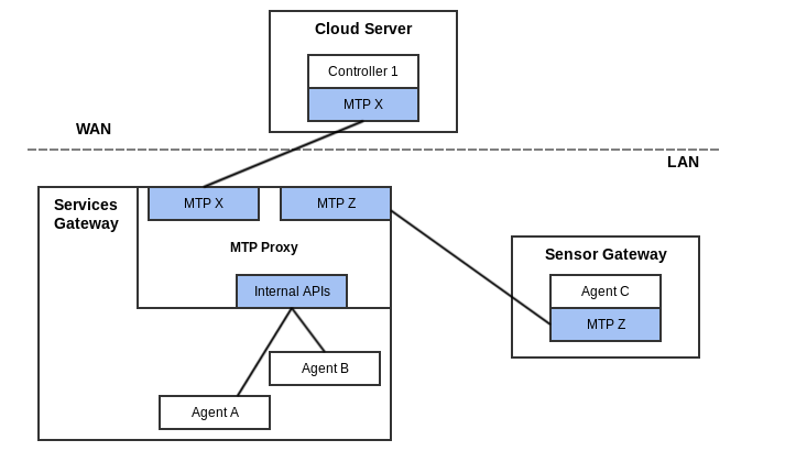
IV.4.2 CoAP / STOMP MTP Proxy Example Message Flow
The following example is provided as a detailed look at a sample CoAP (LAN) / STOMP (WAN) MTP Proxy to describe one possible way to do discovery, connectivity and security. This example makes several assumptions as to the nature of the STOMP connection between the MTP Proxy and the STOMP server, which is completely undefined. It also makes assumptions about implemented, enabled and configured Agent capabilities.
Assumptions include: * a STOMP connection per proxied device * the STOMP server supplies a subscribe-dest header in CONNECTED frames (this is optional for a STOMP server) * there exists some means for the Controller to discover the proxied Agent connection to the STOMP server * the CoAP Agent does mDNS advertisement (optional but recommended behavior) * the CoAP Agent and Proxy support and have enabled DTLS * the CoAP Agent has been configured with the Proxy’s certificate for use as a Trusted Broker. * the proxy uses the subscribe-dest value (supplied by the STOMP server) as the value for the reply-to-dest header.
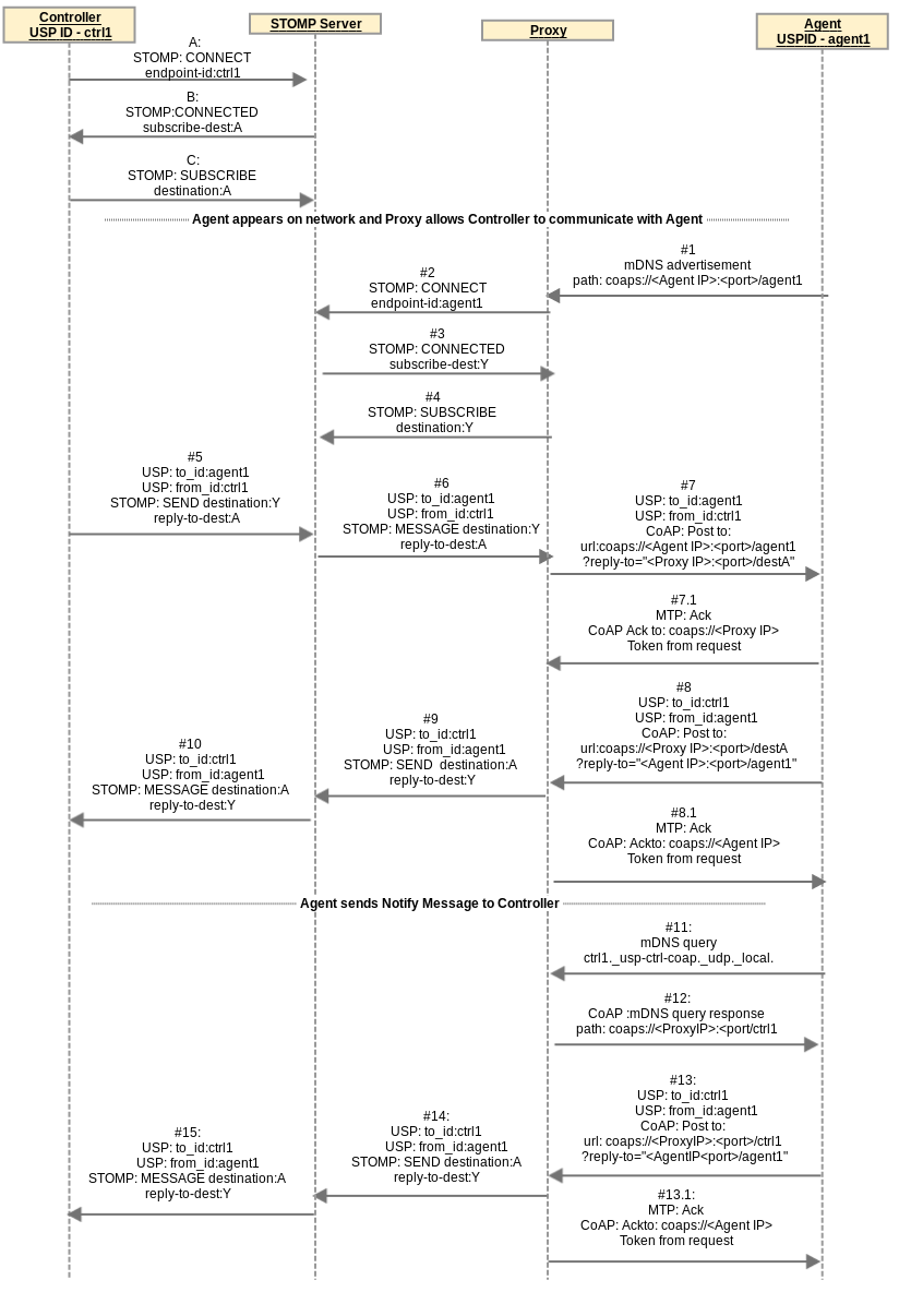
Controller connects to the STOMP server
A / B / C At any point prior to #5 the USP Controller Endpoint ctrl1 connects to STOMP and subscribes to destination A
- OUT OF SCOPE how the USP Endpoint ctrl1 destination A is discovered by Proxy
- OUT OF SCOPE how the proxied USP Endpoint agent1 STOMP destination Y is discovered by USP Endpoint ctrl1
Agent appears on network and Proxy allows Controller to communicate with Agent
#1 The USP Endpoint agent1 appears on the network. Proxy receives advertisement and gets the USP Endpoint identifier “agent1” of the Agent (retrieved from mDNS advertisement see R-DIS.8).
#2 Proxy sends a CONNECT frame to the STOMP server with endpoint-id header of “agent1”.
#3 Proxy receives a subscribe-dest header in the CONNECTED frame identifying the STOMP destination it needs to subscribe to on behalf of agent1.
#4 The Proxy sends a SUBSCRIBE frame to the STOMP server with destination:Y and stores a mapping of USP Endpoint agent1 with coaps://<Agent IP>:<port>/agent1 to this STOMP connection with destination Y.
#5 / #6 USP Endpoint ctrl1 initiates USP message to agent. Proxy creates a STOMP reply-to-dest:A (on this STOMP connection) to coaps://<Proxy IP>:<port>/destA mapping.
#7/ #7.1 Proxy takes USP Record from the STOMP frame and sends it in a CoAP payload with CoAP URI coming from the step #4 mapping of STOMP destination Y to coap://<Agent IP>:<port>/agent1. To secure the communication, the proxy and Agent establish a DTLS session (exchange certificates) and the Agent determines whether the proxy is a Trusted Broker.
#8 / #8.1 USP Endpoint agent1 sends a USP Record in reply to ctrl1 using CoAP, to coaps://<Proxy IP>:<port>/destA.
#9 / #10 Proxy takes USP Record from the CoAP payload and sends it in a STOMP SEND frame using the mapping (created in steps #5 / #6) of coaps://<Proxy IP>:<port>/destA to STOMP destination A (and associated STOMP connection) created in steps #5 / #6 .
Agent sends Notify Message to Controller
These steps include the following additional assumptions: * Controller has configured Agent with a notification subscription. * Controller configured Agent with CoAP MTP information for itself. * Proxy replies to mDNS queries for Controller with “ctrl1” Instance. Controller was able to assume or otherwise determine that Proxy would do this and that its proxied CoAP connection would be discoverable by querying for ctrl1._usp-ctrl-coap._udp._local. * Proxy can use the previous reply-to-dest header value to reach this Controller
#11 The Agent sends mDNS query for ctrl1._usp-ctrl-coap._udp._local.
#12 The Proxy response to the Agent includes TXT record with path of coaps://<Proxy IP>:<port>/ctrl1. This provides a URL for the Agent to use to send a Notify Message to the Controller.
#13 / #13.1 The Agent sends a Notify Message to Controller at coaps://<Proxy IP>:<port>/ctrl1.
#14 / #15 Proxy takes the USP Record from the CoAP payload and sends it in a STOMP SEND frame using the mapping (stored in #5 / #6 ) of coaps://<Proxy IP>:<port>/destA to STOMP destination:A (and associated STOMP connection).
IV.5 USP to Non-USP Proxy
This describes proxying between a Controller and some other
management protocol with its own data model schema (e.g., UPnP DM,
ZigBee, NETCONF, RESTCONF). In this case the proxy is expected to
maintain a USP representation of the non-USP data. This requires the
proxy to expose itself as a full Agent to the Controller. See the Device Proxy appendix for
the Theory of Operations for the Device.ProxiedDevice.
Object defined in the Device:2 Data Model [3].
In order to serve as a USP to non-USP Proxy, the USP to non-USP Translation Function (from Table 1) is needed.
Appendix V: IoT Data Model Theory of Operation
V.1 Introduction
Since there are thousands of different Internet of Things (IoT) devices, the data model needs a flexible modular way to support them using generic building block templates. To achieve this, an IoT device is represented in the data model by sensor and control capabilities:
- Sensor capabilities, which allow reading a state, e.g. a temperature value, a battery level, a light color, etc.
- Control capabilities, which allow changing a value, e.g. set a temperature, switch a light etc.
The Device:2 Data Model [3] defines capability Objects that reflect capabilities found on many different devices (example: BinaryControl). By using these Objects, a large ecosystem of devices can be described using a small set of capabilities (see table below).
V.2 IoT data model overview
The figure shows the overall structure of the IoT data model:
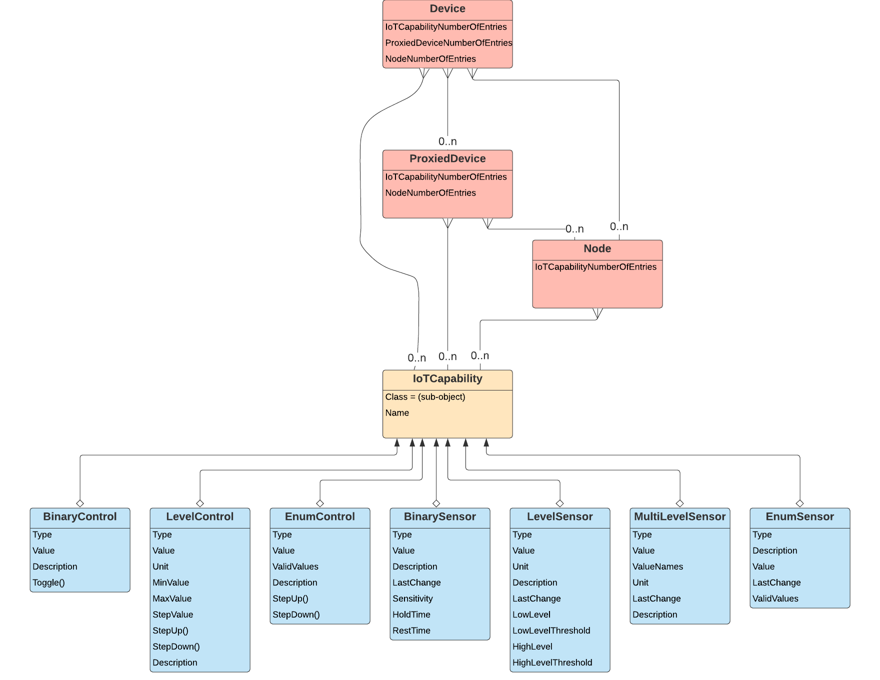
The data model defines an IoT Capability table, whose instances
describe the IoT device’s exposed capabilities. The capability table can
appear directly under the Device. Object (if the IoT device
hosts a USP Agent) or under a Device.ProxiedDevice.{i}. or
Device.ProxiedDevice.{i}.Node.{i}. instance.
V.2.1 IoT Capability table
A capability is represented in the Device.IoTCapability.
table as a generic Object Instance with a specific class, and an
instantiated Sub-Object depending on this class. The class name is
defined by the Sub-Object name in a Class Parameter for
each IoT Capability table entry, to allow the Controller to detect the
instantiated Sub-Object.
Only one out of the following Sub-Objects can exist per instance:
| Capability Sub-Object | Description |
|---|---|
BinaryControl |
Allows setting a binary value (e.g. on or off) |
LevelControl |
Allows setting a continuous value in a predefined range |
EnumControl |
Allows setting a value from a predefined set of values |
BinarySensor |
Provides a binary reading value (true/false) |
LevelSensor |
Provides a continuous reading value |
MultiLevelSensor |
Provides multiple reading values, which belong together |
Each IoT capability Sub-Object has a Type Parameter to
identify the functionality the capability is representing. See the Type definition section
for details.
V.2.2 Node Object table
The Device.Node.{i}. and
Device.ProxiedDevice.{i}.Node.{i}. Objects are mount points
that provide the ability to support complex devices - that is, a group
of capabilities. Each node is a container for a group of device
capabilities that have a direct relationship with each other
(sub-device) and a hierarchal relationship with the top-level. A node
may have the same capabilities as the top-level, but applicable only for
the node, with no impact to the top-level. Capabilities for the
top-level node may have an effect on the lower level nodes, such as
power.
V.3 Architecture mappings
V.3.1 Individual IoT devices
Stand-alone IoT devices, which are capable of supporting their own USP Agent, provide their own data models, which expose the IoT sensor and control capabilities of the device:
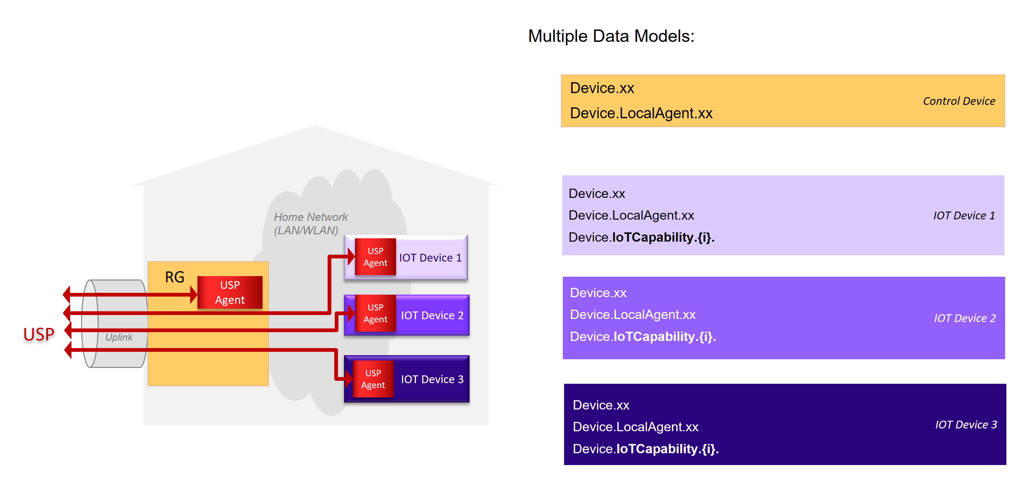
Each device registers as an individual entity to the USP Controller.
With the help of Node Objects, the capabilities can be
additionally structured (not shown in the picture).
V.3.2 Proxied IoT devices
IoT devices connected over a proxy protocol (e.g. ZigBee) with an IoT
control device hosting the USP Agent are modeled as proxied devices
(i.e., using the Device.ProxiedDevice. table) in the data
model of the control device’s USP Agent:
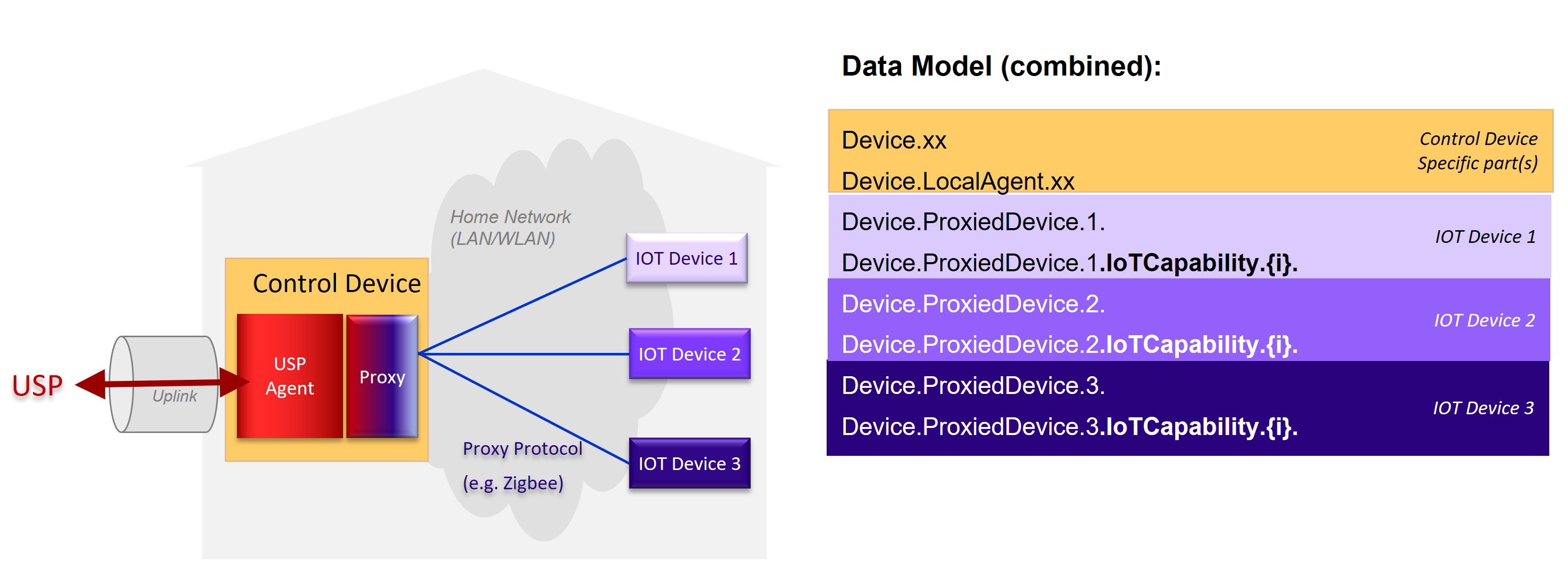
Each IoT device is represented as a
Device.ProxiedDevice.{i}. instance in the data model of the
control device, which exposes its IoT capabilities in the corresponding
Objects. The capabilities can be additionally structured with the help
of Node Object (not shown in the picture).
V.4 IoT data model Object details
V.4.1 Common capability Parameters
These Parameters have the same behavior for all capability Sub-Objects, where defined.
V.4.1.1 Type definition
Applies to: All capability Sub-Objects
All capability Objects contain a mandatory Type
enumeration value.
The Type value is a predefined enumeration value with
the goal of giving a unified description of the capability Object. If
the Type value requires further detail, the
Description Parameter may provided a further
definition.
Note: The Type enumeration in the data model can
also, like all Parameters, be extended using the rules defined in TR-106
[2].
V.4.1.2 Unit definition
Applies to: LevelControl, LevelSensor, MultilevelSensor
To define the used unit a similar concept as for the type definition
is used. The definition consists of the Unit enumeration
value.
The Unit value is a predefined enumeration value with
the goal of giving a unified representation of the used unit.
Note: The Unit enumeration in the data model can
also, like all Parameters, be extended using the rules defined in TR-106
[2].
Note: Imperial units are intentionally not modeled in favor of the metric system to increase the inter-working. If the Controller needs imperial units, it can easily convert the metric units into imperial ones by using the well-defined conversion routines.
V.4.2 Control Objects
Control Objects represent IoT capabilities that involve the manipulation of device or application states. They include Binary Controls, Level Controls, and Enumerated Controls.
V.4.2.1 BinaryControl
The binary controller defines the simplest type of controller, which
allows to switch between two values like true/false, on/off, full/empty,
etc. Its value is modeled as a Boolean, which can be either
true or false.
The minimum definition of a “BinaryControl” consists of:
    IoTCapability.i.Class               = "BinaryControl"
    IoTCapability.i.BinaryControl.Type  = ...
    IoTCapability.i.BinaryControl.Value = ...
The value can be changed either directly by a USP Set operation, or
via The Toggle() command, which corresponds to the behavior
of a switch, changing the value to the other state.
V.4.2.2 LevelControl
The level controller capability allows a continuous change of a value within a predefined range. Its capabilities are defined by these three mandatory Parameters:
Unit- The unit used for the valueMinValue- The minimum value the value can be setMaxValue- The maximum value the value can be set
Implementations have to provide the minimum and maximum values to allow the controller to detect what values can be applied.
The minimum definition of a “LevelControl” consists of:
    IoTCapability.i.Class                 = "LevelControl"
    IoTCapability.i.LevelControl.Type     = ...
    IoTCapability.i.LevelControl.Unit     = ...
    IoTCapability.i.LevelControl.MinValue = ...
    IoTCapability.i.LevelControl.MaxValue = ...
    IoTCapability.i.LevelControl.Value    = ...
The value can be changed either directly by a USP Set operation, or via the step commands.
If the StepUp() command and/or the
StepDown() command are implemented, the
StepValue Parameter has to be implemented, which indicates
the amount of change triggered by a step command. If resulting value of
a step command would exceed the defined range, the operation does not
result in a failure - instead, the result is set to the range limit
value.
For example, if a temperature range is defined from 5.5 degC to 25 degC with a step value of 1 degC, a step down from 6 degC would result in 5.5 degC and not in 5 degC.
Additionally, if the lowest possible value is already set, a
StepDown() will not change the current value, since the
defined minimum range would be exceeded. The same also applies to the
maximum value and StepUp() command.
V.4.2.3 EnumControl
The enumeration controller capability allows setting one of a set of predefined values. Examples are mode selections, with more than two modes. If only two values exist, the binary controller Object is preferred.
The minimum definition of an “EnumControl” consists of:
    IoTCapability.i.Class                   = "EnumControl"
    IoTCapability.i.EnumControl.Type        = ...
    IoTCapability.i.EnumControl.ValidValues = <list of possible values>
    IoTCapability.i.EnumControl.Value       = <current value>
The value can be changed either directly by a USP Set operation, or via the step commands.
The step commands will cycle through the value range, meaning that if
the last valid value is reached, the next StepUp() command
will select the first value of the valid values and vice versa for the
StepDown() command. The valid values are stored in the
Parameter ValidValues as a comma-separated list; that order
of the list will be followed by the step commands.
It is possible to implement only one of the step commands, if only one direction is needed.
V.4.3 Sensor Objects
Sensor Objects represent IoT capabilities that involve reading or reporting on a device or application state. They include Binary Sensors, Level Sensors, and Enumerated Sensors, along with support for thresholds and triggering events.
V.4.3.1 Binary Sensor
The binary sensor Object Instance supports different kinds of binary sensor operations:
- Simple binary state, e.g. a door or window state
- Threshold trigger, e.g. trigger a Carbon Dioxide Alarm if a certain threshold is exceeded.
- Repeated trigger with grace period, e.g. movement detector.
V.4.3.1.1 Simple binary state sensor
To model a simple sensor, which changes between two distinct states
(e.g. a window or door open/close sensor), only the Value
Parameter is needed.
The minimum definition of a BinarySensor consists of:
    IoTCapability.i.Class              = "BinarySensor"
    IoTCapability.i.BinarySensor.Type  = ...
    IoTCapability.i.BinarySensor.Value = {true/false}
The values of true and false represent the
two possible Value states. Each time the state changes the
value toggles.
For example, a motion sensor would be modeled as:
    IoTCapability.i.Class              = "BinarySensor"
    IoTCapability.i.BinarySensor.Type  = "MotionDetected"
    IoTCapability.i.BinarySensor.Value = true
Note that binary sensor types are meaningful for binary state behavior, e.g., “WindowOpen” rather than “Window”.
V.4.3.1.2 Threshold trigger sensor
To model a sensor, which additionally triggers on a certain
threshold, add the Sensitivity Parameter to the
definition:
    IoTCapability.1.Class                    = "BinarySensor"
    IoTCapability.1.BinarySensor.Type        = "CarbonDioxideDetected"
    IoTCapability.1.BinarySensor.Value       = {true/false}
    IoTCapability.1.BinarySensor.Sensitivity = 50
With the Sensitivity Parameter, the threshold is
controlled. As soon as the measured value exceeds the threshold, the
Value Parameter is set to true. As soon as the
measured value goes below the threshold the Value Parameter
is set to false.
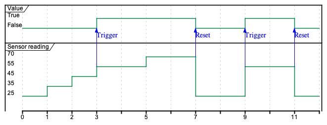
The sensitivity value is a relative value in the range 0 to 100 percent. The exact meaning depends on the implementation.
V.4.3.1.3 Trigger time control
If the sensor state, after being triggered, should stay active for a
minimum period, the HoldTime Parameter is used:
    IoTCapability.1.Class                    = "BinarySensor"
    IoTCapability.1.BinarySensor.Type        = "CarbonDioxideDetected"
    IoTCapability.1.BinarySensor.Value       = {true/false}
    IoTCapability.1.BinarySensor.Sensitivity = 50
    IoTCapability.1.BinarySensor.HoldTime    = 5000
This figure shows the effect of the HoldTime Parameter
on the resulting value:
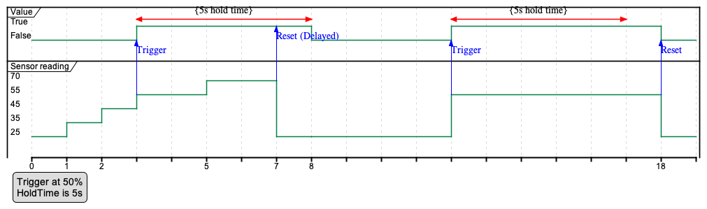
If the HoldTime Parameter is not implemented or is set
to 0, the handling is disabled.
V.4.3.1.4 Repeated trigger with grace period
Some sensors might produce too many triggers, e.g. continuous
movement, when only one trigger in a specific time period is needed. To
filter these the RestTime Parameter is used:
    IoTCapability.1.Class                    = "BinarySensor"
    IoTCapability.1.BinarySensor.Type        = "CarbonDioxideDetected"
    IoTCapability.1.BinarySensor.Value       = {true/false}
    IoTCapability.1.BinarySensor.Sensitivity = 50
    IoTCapability.1.BinarySensor.RestTime    = 10000
With this setting, new trigger events are ignored for 10 seconds (10000 miliseconds) after the first trigger has been detected, resulting in the following pattern:
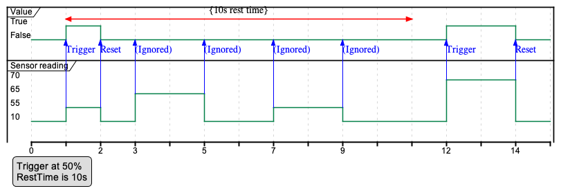
If the RestTime Parameter is not implemented or is set
to 0, the handling is disabled.
V.4.3.1.5 Repeated trigger with minimum duration
To get readings with a minimum duration, combine rest and hold times:
    IoTCapability.1.Class                    = "BinarySensor"
    IoTCapability.1.BinarySensor.Type        = "CarbonDioxideDetected"
    IoTCapability.1.BinarySensor.Value       = {true/false}
    IoTCapability.1.BinarySensor.Sensitivity = 50
    IoTCapability.1.BinarySensor.HoldTime    = 5000
    IoTCapability.1.BinarySensor.RestTime    = 10000
Which results in the following pattern:
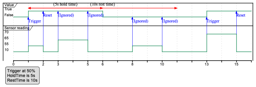
V.4.3.2 Level Sensor
The LevelSensor Object provides a template for modeling
devices that report various levels. LevelSensor is used to
reflect the functionality of a sensor that reports a level in units and
supports different kinds of sensor operation:
- Level reading
- Additional Threshold trigger: e.g., a Battery Alarm is triggered.
V.4.3.2.1 Level reading
To model a level reading, the reading value and its unit are defined.
The minimum definition of a LevelSensor consists of:
    IoTCapability.i.Class             = "LevelSensor"
    IoTCapability.i.LevelSensor.Type  = ...
    IoTCapability.i.LevelSensor.Unit  = ...
    IoTCapability.i.LevelSensor.Value = ...
For example, to show the remaining load of a battery in percent, this capability would have the following values:
    IoTCapability.1.Class             = "LevelSensor"
    IoTCapability.1.LevelSensor.Type  = "Battery"
    IoTCapability.1.LevelSensor.Unit  = "%"
    IoTCapability.1.LevelSensor.Value = 63"
With this definition, the remaining load is expressed in percent, here 63 percent. Since the unit value is a decimal type it is also possible to specify fractions for the value:
    IoTCapability.1.Class             = "LevelSensor"
    IoTCapability.1.LevelSensor.Type  = "Battery"
    IoTCapability.1.LevelSensor.Unit  = "%"
    IoTCapability.1.LevelSensor.Value = 63.26
This expresses a total remaining load of 63.26 percent.
V.4.3.2.2 Threshold trigger
In cases where not only the actual value is of interest, but also
important to know if a predefined threshold is reached or undershot, the
LevelSensor Object can be extended with threshold
Parameters. Once the LowLevel or HighLevel
Parameter is true, it will remain true until
the device is reset or the condition no longer exists. This will depend
on the particular device.
| Parameter | Type | R/W | Description |
|---|---|---|---|
LowLevel |
boolean | R | True means that the low level threshold is reached or undershot. |
LowLevelThreshold |
decimal | R/W | The defined low level value. |
HighLevel |
boolean | R | True means that the high level threshold is reached or exceeded. |
HighLevelThreshold |
decimal | R/W | The defined high level value. |
Table 17 – IoT LevelSensor threshold Parameters
When modeling a battery with a LevelSensor Object, an
additional low level warning (Boolean) may be supported along with a Low
Level threshold that provides a setting for the warning. The resulting
Object looks like this:
    IoTCapability.1.Class                         = "LevelSensor"
    IoTCapability.1.LevelSensor.Type              = "Battery"
    IoTCapability.1.LevelSensor.Unit              = "%"
    IoTCapability.1.LevelSensor.LowLevelThreshold = 20
    IoTCapability.1.LevelSensor.Value             = 19
    IoTCapability.1.LevelSensor.LowLevel          = true
Note: For more complex scenarios, like having a grace period, the binary sensor Object can be used instead of the LowLevel or HighLevel Threshold Parameters.
V.4.3.2.3 Multi Level Sensor
A MultiLevelSensor instance models sensors, which
provide a set of related values with the same unit.
The minimum definition of a “MultiLevelSensor” consists of:
    IoTCapability.i.Class                       = "MultiLevelSensor"
    IoTCapability.i.MultiLevelSensor.Type       = ...
    IoTCapability.i.MultiLevelSensor.Unit       = ...
    IoTCapability.i.MultiLevelSensor.Values     = ...
    IoTCapability.i.MultiLevelSensor.ValueNames = ...
An example is a location reading consisting of the two values longitude and latitude in decimal degree notation, which have to be read together:
    IoTCapability.1.Class                       = "MultiLevelSensor"
    IoTCapability.1.MultiLevelSensor.Type       = "Location"
    IoTCapability.1.MultiLevelSensor.Unit       = "deg"
    IoTCapability.1.MultiLevelSensor.Values     = "48.1372056,11.57555"
    IoTCapability.1.MultiLevelSensor.ValueNames = "Latitude,Longitude"
This example uses the Parameter ValueNames to provide
information about the individual value meanings.
V.4.3.3 Enum Sensor
An EnumSensor instance provides a reading value from a
predefined set of values. This allows modeling of sensors, which can
output discreet values from a predefined set.
The minimum definition of an “EnumSensor” consists of:
    IoTCapability.i.Class                  = "EnumSensor"
    IoTCapability.i.EnumSensor.Type        = ...
    IoTCapability.i.EnumSensor.Unit        = ...
    IoTCapability.i.EnumSensor.ValidValues = ...
    IoTCapability.i.EnumSensor.Value       = ...
The ValidValues Parameter determines the set of values,
which will be delivered by the sensor.
For example, a traffic light could be modeled as:
    IoTCapability.1.Class                  = "EnumSensor"
    IoTCapability.1.EnumSensor.Type        = "X_<oui>_TrafficLight"
    IoTCapability.1.EnumSensor.ValidValues = "Red, Yellow, Green"
    IoTCapability.1.EnumSensor.Value       = "Green"
V.4.4 IoTCapability Binding
The IoTCapability Binding mechanism provides a path to route IoT data from Sensor IoTCapabilities to Control IoTCapabilities. This concept supports data flow orchestration between sensors and actuators.
When an event (e.g., motion, temperature change, or status update) is encountered, the Value parameter of the Sensor IoTCapability is updated. If a binding is configured and enabled, the Value parameter of the specified Control IoTCapability instance is updated with the value provided by the Sensor IoTCapability. See Example: Remote Motion Sensor Binding to a Remote Control and Example: Native Motion Sensor Binding to a Remote Control.
The Binding definition may only exist on a Sensor IoTCapability binding it to a Control IoTCapability of a equivalent class. The following binding may be established:
- BinarySensor IoTCapability –> BinaryControl IoTCapability
- LevelSensor IoTCapability –> LevelControl IoTCapability
- EnumSensor IoTCapability –> EnumControl IoTCapability
- PulseSensor IoTCapability –> PulseControl IoTCapability
V.5 Examples
This chapter gives several examples how to model IoT Devices.
V.5.1 Example: A/C Thermostat
This example shows an A/C Thermostat connected over Z-Wave as a proxied device of an IoT Gateway:
Structure elements:
- IoTCapability.1 (EnumControl) : Operation Mode
- IoTCapability.2 (LevelControl) : Cool Temperature in range from 14 to 25 degC
- IoTCapability.3 (LevelControl) : Heat Temperature in range from 14 to 25 degC
- IoTCapability.4 (LevelControl) : Energy Saving Cool Temperature in range from 14 to 25 degC
- IoTCapability.5 (LevelControl) : Energy Saving Heat Temperature in range from 14 to 25 degC
- IoTCapability.6 (LevelSensor) : Current Temperature
- IoTCapability.7 (EnumControl) : Fan Mode Control
- IoTCapability.8 (EnumSensor) : Current Fan Operating State
Instantiated data model:
    Device.ProxiedDevice.1.Type                                    = "Thermostat"
    Device.ProxiedDevice.1.Online                                  = true
    Device.ProxiedDevice.1.ProxyProtocol                           = "Z-Wave"

    Device.ProxiedDevice.1.IoTCapabilityNumberOfEntries            = 9

    Device.ProxiedDevice.1.IoTCapability.1.Class                   = "EnumControl"
    Device.ProxiedDevice.1.IoTCapability.1.EnumControl.Type        = "ThermostatMode"
    Device.ProxiedDevice.1.IoTCapability.1.EnumControl.Value       = "Cool"
    Device.ProxiedDevice.1.IoTCapability.1.EnumControl.ValidValues = "Heat, Cool,
                                                                     Energy_heat,
                                                                     Energy_cool, Off,
                                                                     Auto"

    Device.ProxiedDevice.1.IoTCapability.2.Class                   = "LevelControl"
    Device.ProxiedDevice.1.IoTCapability.2.LevelControl.Type       = "Temperature"
    Device.ProxiedDevice.1.IoTCapability.2.LevelControl.Description = "TargetCoolTemperature"
    Device.ProxiedDevice.1.IoTCapability.2.LevelControl.Value      = 17
    Device.ProxiedDevice.1.IoTCapability.2.LevelControl.Unit       = "degC"
    Device.ProxiedDevice.1.IoTCapability.2.LevelControl.MinValue   = 14
    Device.ProxiedDevice.1.IoTCapability.2.LevelControl.MaxValue   = 25

    Device.ProxiedDevice.1.IoTCapability.3.Class                   = "LevelControl"
    Device.ProxiedDevice.1.IoTCapability.3.LevelControl.Type       = "Temperature"
    Device.ProxiedDevice.1.IoTCapability.3.LevelControl.Description = "TargetHeatTemperature"
    Device.ProxiedDevice.1.IoTCapability.3.LevelControl.Value      = 21
    Device.ProxiedDevice.1.IoTCapability.3.LevelControl.Unit       = "degC"
    Device.ProxiedDevice.1.IoTCapability.3.LevelControl.MinValue   = 14
    Device.ProxiedDevice.1.IoTCapability.3.LevelControl.MaxValue   = 25

    Device.ProxiedDevice.1.IoTCapability.4.Class                   = "LevelControl"
    Device.ProxiedDevice.1.IoTCapability.4.LevelControl.Type       = "Temperature"
    Device.ProxiedDevice.1.IoTCapability.4.LevelControl.Description = "TargetEnergyCoolTemp"
    Device.ProxiedDevice.1.IoTCapability.4.LevelControl.Value      = 19
    Device.ProxiedDevice.1.IoTCapability.4.LevelControl.Unit       = "degC"
    Device.ProxiedDevice.1.IoTCapability.4.LevelControl.MinValue   = 14
    Device.ProxiedDevice.1.IoTCapability.4.LevelControl.MaxValue   = 25

    Device.ProxiedDevice.1.IoTCapability.5.Class                   = "LevelControl"
    Device.ProxiedDevice.1.IoTCapability.5.LevelControl.Type       = "Temperature"
    Device.ProxiedDevice.1.IoTCapability.5.LevelControl.Description = "TargetEnergyHeatTemp"
    Device.ProxiedDevice.1.IoTCapability.5.LevelControl.Value      = 19
    Device.ProxiedDevice.1.IoTCapability.5.LevelControl.Unit       = "degC"
    Device.ProxiedDevice.1.IoTCapability.5.LevelControl.MinValue   = 14
    Device.ProxiedDevice.1.IoTCapability.5.LevelControl.MaxValue   = 25

    Device.ProxiedDevice.1.IoTCapability.6.Class                   = "LevelSensor"
    Device.ProxiedDevice.1.IoTCapability.6.LevelSensor.Type        = "Temperature"
    Device.ProxiedDevice.1.IoTCapability.6.LevelSensor.Value       = 19.5
    Device.ProxiedDevice.1.IoTCapability.6.LevelSensor.Unit        = "degC"

    Device.ProxiedDevice.1.IoTCapability.7.Class                   = "EnumControl"
    Device.ProxiedDevice.1.IoTCapability.7.EnumControl.Type        = "FanMode"
    Device.ProxiedDevice.1.IoTCapability.7.EnumControl.Value       = "Low"
    Device.ProxiedDevice.1.IoTCapability.7.EnumControl.ValidValues = "Auto_low, Low,
                                                              Circulation, Off"

    Device.ProxiedDevice.1.IoTCapability.8.Class                   = "EnumSensor"
    Device.ProxiedDevice.1.IoTCapability.8.EnumSensor.Type         = "OperatingState"
    Device.ProxiedDevice.1.IoTCapability.8.EnumSensor.Value        = "Cooling"
    Device.ProxiedDevice.1.IoTCapability.8.EnumSensor.ValidValues  =
                              "Heating, Cooling,
                              FanOnly, PendingHeat, PendingCool, VentEconomizer,
                              AuxHeating, 2ndStageHeating, 2ndStageCooling,
                              2ndStageAuxHeat, 3rdStageAuxHeat"
V.5.2 Example: Light with a dimmer and switch
This example shows a dimmable light connected over Z-Wave as proxied device to an IoT Gateway.
Structure elements:
- IoTCapability.1 (BinaryControl) : On/Off Switch, expressed as
trueandfalsevalue - IoTCapability.2 (LevelControl) : Brightness control from 0% to 100%
Instantiated data model:
    Device.ProxiedDevice.2.Type                                      = "Light"
    Device.ProxiedDevice.2.Online                                    = "true"
    Device.ProxiedDevice.2.ProxyProtocol                             = "Z-Wave"
    Device.ProxiedDevice.2.Name                                      = "GE DimMing Bulb"
    Device.ProxiedDevice.2.IoTCapabilityNumberOfEntries              = 2

    Device.ProxiedDevice.2.IoTCapability.1.Class                     = "BinaryControl"
    Device.ProxiedDevice.2.IoTCapability.1.BinaryControl.Type        = "Switch"
    Device.ProxiedDevice.2.IoTCapability.1.BinaryControl.Value       = true

    Device.ProxiedDevice.2.IoTCapability.2.Class                     = "LevelControl"
    Device.ProxiedDevice.2.IoTCapability.2.LevelControl.Type         = "Brightness"
    Device.ProxiedDevice.2.IoTCapability.2.LevelControl.Value        = 100
    Device.ProxiedDevice.2.IoTCapability.2.LevelControl.Min          = 0
    Device.ProxiedDevice.2.IoTCapability.2.LevelControl.Max          = 100
    Device.ProxiedDevice.2.IoTCapability.2.LevelControl.Unit         = "%"
V.5.3 Example: Fan
This example shows a simple fan connected over Z-Wave as proxied device to an IoT Gateway.
Structure elements:
- IoTCapability.1 (EnumControl) : Fan state
Instantiated data model:
    Device.ProxiedDevice.3.Type                                       = "Fan"
    Device.ProxiedDevice.3.Online                                     = "true"
    Device.ProxiedDevice.3.ProxyProtocol                              = "Z-Wave"
    Device.ProxiedDevice.3.name                                       = "GE Fan"
    Device.ProxiedDevice.3.IoTCapabilityNumberOfEntries               = 1

    Device.ProxiedDevice.2.IoTCapability.1.Class                      = "EnumControl"
    Device.ProxiedDevice.3.IoTCapability.1.EnumControl.Type           = "FanMode"
    Device.ProxiedDevice.3.IoTCapability.1.EnumControl.Value          = "Off"
    Device.ProxiedDevice.3.IoTCapability.1.EnumControlValidValues     =
                                   "Off, Low, Medium, High, On, Auto, Smart"
V.5.4 Example: Multi-Sensor strip with a common battery.
The sensors are inserted into the strip and may have their own power switch, battery, energy consumption and manufacturer.
Instantiated data model:
    Device.ProxiedDevice.4.Type                                             = "SensorStrip"
    Device.ProxiedDevice.4.Online                                           = true
    Device.ProxiedDevice.4.ProxyProtocol                                    = "Z-Wave"
    Device.ProxiedDevice.4.Name                                             = "Insertable Sensor Strip"
    Device.ProxiedDevice.4.IoTCapabilityNumberOfEntries                     = 1
    Device.ProxiedDevice.4.NodeNumberOfEntries                              = 2

    Device.ProxiedDevice.4.IoTCapability.1.Class                            = "LevelSensor"
    Device.ProxiedDevice.4.IoTCapability.1.LevelSensor.Value                = 80
    Device.ProxiedDevice.4.IoTCapability.1.LevelSensor.Unit                 = "%"
    Device.ProxiedDevice.4.IoTCapability.1.LevelSensor.Type                 = "Battery"
    Device.ProxiedDevice.4.IoTCapability.1.LevelSensor.LowLevelThreshold    = 30
    Device.ProxiedDevice.4.IoTCapability.1.LevelSensor.LowLevel             = false

    Device.ProxiedDevice.4.Node.1.Type                                      = "Sensor"
    Device.ProxiedDevice.4.Node.1.IoTCapabilityNumberOfEntries              = 1

    Device.ProxiedDevice.4.Node.1.IoTCapability.1.Class                     = "BinarySensor"
    Device.ProxiedDevice.4.Node.1.IoTCapability.1.BinarySensor.HoldTime     = 0
    Device.ProxiedDevice.4.Node.1.IoTCapability.1.BinarySensor.Sensitivity  = 5
    Device.ProxiedDevice.4.Node.1.IoTCapability.1.BinarySensor.RestTime     = 10000
    Device.ProxiedDevice.4.Node.1.IoTCapability.1.BinarySensor.Value        = false
    Device.ProxiedDevice.4.Node.1.IoTCapability.1.BinarySensor.Type         = "MotionDetected"
    Device.ProxiedDevice.4.Node.1.IoTCapability.1.BinarySensor.LastSensingTime  = 1573344000
V.5.5 Example: Ceiling Fan with integrated light
This example shows a ceiling fan with integrated light connected over Z-Wave as proxied device to an IoT Gateway.
Structure elements:
- IoTCapability.1 (BinaryControl) :
- Node.1 : Represents the light control
- .IoTCapability.1 (LevelControl) : Brightness control from 0% to 100%
- .IoTCapability.2 (BinaryControl) : On/Off Switch, expressed as
trueandfalsevalue - Node.2 : Fan control
- .IoTCapability.1 (EnumControl) : Set fan state
Instantiated data model:
    Device.ProxiedDevice.5.Type                                           = "Fan"
    Device.ProxiedDevice.5.Online                                         = true
    Device.ProxiedDevice.5.ProxyProtocol                                  = "Z-Wave"
    Device.ProxiedDevice.5.Name                                           = "42'' Ceiling Fan"

    Device.ProxiedDevice.5.IoTCapabilityNumberOfEntries                   = 1
    Device.ProxiedDevice.5.NodeNumberOfEntries                            = 2

    Device.ProxiedDevice.5.IoTCapability.1.Class                          = "BinaryControl"
    Device.ProxiedDevice.5.IoTCapability.1.BinaryControl.Type             = "Switch"
    Device.ProxiedDevice.5.IoTCapability.1.BinaryControl.State            = true

    Device.ProxiedDevice.5.Node.1.Type                                    = "Light"
    Device.ProxiedDevice.5.Node.1.IoTCapabilityNumberOfEntries            = 2

    Device.ProxiedDevice.5.Node.1.IoTCapability.1.Class                   = "LevelControl"
    Device.ProxiedDevice.5.Node.1.IoTCapability.1.LevelControl.Type       = "Brightness"
    Device.ProxiedDevice.5.Node.1.IoTCapability.1.LevelControl.Value      = 99
    Device.ProxiedDevice.5.Node.1.IoTCapability.1.LevelControl.MinValue   = 0
    Device.ProxiedDevice.5.Node.1.IoTCapability.1.LevelControl.MaxValue   = 100
    Device.ProxiedDevice.5.Node.1.IoTCapability.1.LevelControl.Unit       = "%"

    Device.ProxiedDevice.5.Node.1.IoTCapability.2.Class                   = "BinaryControl"
    Device.ProxiedDevice.5.Node.1.IoTCapability.2.BinaryControl.Type      = "Switch"
    Device.ProxiedDevice.5.Node.1.IoTCapability.2.BinaryControl.Value     = true

    Device.ProxiedDevice.5.Node.2.Type                                    = "Fan"
    Device.ProxiedDevice.5.Node.2.IoTCapabilityNumberOfEntries            = 1

    Device.ProxiedDevice.5.Node.2.IoTCapability.1.Class                   = "EnumControl"
    Device.ProxiedDevice.5.Node.2.IoTCapability.1.EnumControl.Type        = "FanMode"
    Device.ProxiedDevice.5.Node.2.IoTCapability.1.EnumControl.Value       = "Off"
    Device.ProxiedDevice.5.Node.2.IoTCapability.1.EnumControl.ValidValues = "Off, Low,
                                                                         Medium, High,
                                                                         Auto, Smart
V.5.6 Example: Power strip
This example shows a power strip with integrated power measurements connected over Z-Wave as proxied device to an IoT Gateway.
Structure elements:
- IoTCapability.1 (BinaryControl) : On/Off Switch for complete power strip
- IoTCapability.2 (LevelSensor) : Total power reading of strip in KWh.
- Node.1 - 3: Each node represents a power outlet with:
- .IoTCapability.1 (BinaryControl) : On/Off Switch, expressed as
trueandfalsevalue - .IoTCapability.2 (LevelSensor) : Current power reading of outlet in Watt.
- .IoTCapability.3 (LevelSensor) : Total used power reading of outlet in KWh.
- .IoTCapability.1 (BinaryControl) : On/Off Switch, expressed as
Instantiated data model:
    Device.ProxiedDevice.6.Type                                         = "PowerStrip"
    Device.ProxiedDevice.6.Online                                       = "true"
    Device.ProxiedDevice.6.ProxyProtocol                                = "Z-Wave"
    Device.ProxiedDevice.6.Name                                         = "3 Plug Strip"
    Device.ProxiedDevice.6.IoTCapabilityNumberOfEntries                 = 2
    Device.ProxiedDevice.6.NodeNumberOfEntries                          = 3

    Device.ProxiedDevice.6.IoTCapability.1.Class                        = "BinaryControl"
    Device.ProxiedDevice.6.IoTCapability.1.BinaryControl.Type           = "Switch"
    Device.ProxiedDevice.6.IoTCapability.1.BinaryControl.Value          = true
    Device.ProxiedDevice.6.IoTCapability.3.Class                        = "LevelSensor"
    Device.ProxiedDevice.6.IoTCapability.3 Name                         = "Total Accumulated Power"
    Device.ProxiedDevice.6.IoTCapability.3.LevelSensor.Type             = "Power"
    Device.ProxiedDevice.6.IoTCapability.3.LevelSensor.Unit             = "KWh"
    Device.ProxiedDevice.6.IoTCapability.3.LevelSensor.Value            = "2227,56"

    Device.ProxiedDevice.6.Node.1.Type                                  = "Switch"
    Device.ProxiedDevice.6.Node.1.IoTCapabilityNumberOfEntries          = 3
    Device.ProxiedDevice.6.Node.1.IoTCapability.1.Class                 = "BinaryControl"
    Device.ProxiedDevice.6.Node.1.IoTCapability.1.BinaryControl.Type    = "Switch"
    Device.ProxiedDevice.6.Node.1.IoTCapability.1.BinaryControl.State   = true
    Device.ProxiedDevice.6.Node.1.IoTCapability.2.Class                 = "LevelSensor"
    Device.ProxiedDevice.6.Node.1.IoTCapability.2.LevelSensor.Type      = "Power"
    Device.ProxiedDevice.6.Node.1.IoTCapability.2.LevelSensor.Unit      = "W"
    Device.ProxiedDevice.6.Node.1.IoTCapability.2.LevelSensor.Value     = 99
    Device.ProxiedDevice.6.Node.1.IoTCapability.3.Class                 = "LevelSensor"
    Device.ProxiedDevice.6.Node.1.IoTCapability.3 Name                  = "Accumulated Power"
    Device.ProxiedDevice.6.Node.1.IoTCapability.3.LevelSensor.Type      = "Power"
    Device.ProxiedDevice.6.Node.1.IoTCapability.3.LevelSensor.Unit      = "KWh"
    Device.ProxiedDevice.6.Node.1.IoTCapability.3.LevelSensor.Value     = 390.67

    Device.ProxiedDevice.6.Node.2.Type                                  = "Switch"
    Device.ProxiedDevice.6.Node.2.IoTCapabilityNumberOfEntries          = 3
    Device.ProxiedDevice.6.Node.2.IoTCapability.1.Class                 = "BinaryControl"
    Device.ProxiedDevice.6.Node.2.IoTCapability.1.BinaryControl.Type    = "Switch"
    Device.ProxiedDevice.6.Node.2.IoTCapability.1.BinaryControl.State   = true
    Device.ProxiedDevice.6.Node.2.IoTCapability.2.Class                 = "LevelSensor"
    Device.ProxiedDevice.6.Node.2.IoTCapability.2.LevelSensor.Type      = "Power"
    Device.ProxiedDevice.6.Node.2.IoTCapability.2.LevelSensor.Unit      = "W"
    Device.ProxiedDevice.6.Node.2.IoTCapability.2.LevelSensor.Value     = 76
    Device.ProxiedDevice.6.Node.2.IoTCapability.3.Class                 = "LevelSensor"
    Device.ProxiedDevice.6.Node.2.IoTCapability.3 Name                  = "Accumulated Power"
    Device.ProxiedDevice.6.Node.2.IoTCapability.3.LevelSensor.Type      = "Power"
    Device.ProxiedDevice.6.Node.2.IoTCapability.3.LevelSensor.Unit      = "KWh"
    Device.ProxiedDevice.6.Node.2.IoTCapability.3.LevelSensor.Value     = 1783.63

    Device.ProxiedDevice.6.Node.3.Type                                  = "Switch"
    Device.ProxiedDevice.6.Node.3.IoTCapabilityNumberOfEntries          = 3
    Device.ProxiedDevice.6.Node.3.IoTCapability.1.Class                 = "BinaryControl"
    Device.ProxiedDevice.6.Node.3.IoTCapability.1.BinaryControl.Type    = "Switch"
    Device.ProxiedDevice.6.Node.3.IoTCapability.1.BinaryControl.State   = true
    Device.ProxiedDevice.6.Node.3.IoTCapability.2.Class                 = "LevelSensor"
    Device.ProxiedDevice.6.Node.3.IoTCapability.2.LevelSensor.Type      = "Power"
    Device.ProxiedDevice.6.Node.3.IoTCapability.2.LevelSensor.Unit      = "W"
    Device.ProxiedDevice.6.Node.3.IoTCapability.2.LevelSensor.Value     = 0
    Device.ProxiedDevice.6.Node.3.IoTCapability.3.Class                 = "LevelSensor"
    Device.ProxiedDevice.6.Node.3.IoTCapability.3 Name                  = "Accumulated Power"
    Device.ProxiedDevice.6.Node.3.IoTCapability.3.LevelSensor.Type      = "Power"
    Device.ProxiedDevice.6.Node.3.IoTCapability.3.LevelSensor.Unit      = "KWh"
    Device.ProxiedDevice.6.Node.3.IoTCapability.3.LevelSensor.Value     = 53.26
V.5.7 Example: Battery powered radiator thermostat
This example shows the IoT model for a radiator thermostat with an integrated USP Agent, which is directly controlled.
Structure elements:
- IoTCapability.1 (EnumControl): Operation Mode
- IoTCapability.2 (EnumControl): Auto/Manual Temperature setting
- IoTCapability.3 (EnumControl): Vacation Temperature setting
- IoTCapability.4 (LevelSensor) : Current Temperature
- IoTCapability.5 (LevelSensor): Valve position
- IoTCapability.6 (LevelSensor): Battery status
Note: All temperature settings are modeled as “EnumControl” to define a range between 4 and 23° degC in steps of 0.5° or an “Off” value.
Instantiated data model:
    Device.DeviceInfo.Description                  = "Battery powered radiator
                                                      thermostat"

    Device.IoTCapabilityNumberOfEntries            = 6

    Device.IoTCapability.1.Class                   = "EnumControl
    Device.IoTCapability.1.EnumControl.Type        = "ThermostatMode"
    Device.IoTCapability.1.EnumControl.ValidValues = "Off, Auto, Manual, Vacation"
    Device.IoTCapability.1.EnumControl.Value       = "Auto"      # current mode

    Device.IoTCapability.2.Class                   = "EnumControl
    Device.IoTCapability.2.Name                    = "Desired Temperature"
    Device.IoTCapability.2.EnumControl.Type        = "TemperatureMode"
    Device.IoTCapability.2.EnumControl.ValidValues = "Off, 4, 4.5, 5.0, 5.5,
                                                     6, 6.5, 7, 7.5, 8, 8.5,
                                                     9, 9.5, 10, 10.5, 11,
                                                     11.5, 12, 12.5, 13, 13.5,
                                                     14, 14.5, 15.0, 15.5, 16,
                                                     16.5, 17, 17.5, 18, 18.5,
                                                     19, 19.5, 20, 20.5, 21,
                                                     21.5, 22, 22.5, 23"
    Device.IoTCapability.2.EnumControl.Value       = 19   # Requested temperature

    Device.IoTCapability.3.Class                   = "EnumControl"
    Device.IoTCapability.3.Name                    = "Vacation Temperature"
    Device.IoTCapability.3.EnumControl.Type        = "TemperatureMode"
    Device.IoTCapability.3.EnumControl.ValidValues = "Off, 4, 4.5, 5.0, 5.5,
                                                     6, 6.5, 7, 7.5, 8, 8.5,
                                                     9, 9.5, 10, 10.5, 11,
                                                     11.5, 12, 12.5, 13, 13.5,
                                                     14, 14.5, 15.0, 15.5, 16,
                                                     16.5, 17, 17.5, 18, 18.5,
                                                     19, 19.5, 20, 20.5, 21,
                                                     21.5, 22, 22.5, 23"
    Device.IoTCapability.3.EnumControl.Value       = 12   # Requested temperature
                                                            # during absence

    Device.IoTCapability.4.Class                   = "LevelSensor"
    Device.IoTCapability.4.Name                    = "Current Temperature"
    Device.IoTCapability.4.LevelSensor.Type        = "Temperature"
    Device.IoTCapability.4.LevelSensor.Unit        = "degC"
    Device.IoTCapability.4.LevelSensor.Value       = 19.3 # Current temperature

    Device.IoTCapability.5.Class                   = "LevelSensor"
    Device.IoTCapability.5.Name                    = "Valve Position"
    Device.IoTCapability.5.LevelSensor.Type        = "Position"
    Device.IoTCapability.5.LevelSensor.Unit        = "%"
    Device.IoTCapability.5.LevelSensor.MinValue    = 0
    Device.IoTCapability.5.LevelSensor.MaxValue    = 100
    Device.IoTCapability.5.LevelSensor.Value       = 16     # e.g. 16% valve
                                                               # opening

    Device.IoTCapability.6.Class                   = "LevelSensor"
    Device.IoTCapability.6.Name                    = "Local Battery"
    Device.IoTCapability.6.LevelSensor.Type        = "Battery"
    Device.IoTCapability.6.LevelSensor.Unit        = "%"
    Device.IoTCapability.6.LevelSensor.MinValue    = 0
    Device.IoTCapability.6.LevelSensor.MaxValue    = 100
    Device.IoTCapability.6.LevelSensor.Value       = 82      # e.g. 82% battery load
V.5.8 Example: Remote Motion Sensor Binding to a Remote Control
A Motion Sensor, sends its value to the Agent and maps onto ProxiedDevice - IoTCapability Object: “Device.ProxiedDevice.1.IoTCapability.1.”
Via the IoTCapability Binding, this motion sensor value will be forwarded to ProxiedDevice - IoTCapability Object: “Device.ProxiedDevice.2.IoTCapability.1.”
Every time, when the value of the Motion Sensor changes, this new value is received by the LevelSensor IoTCapability of “Device.ProxiedDevice.1.IoTCapability.1.” and due to the binding immediately passed to LevelControl IoTCapability of “Device.ProxiedDevice.2.IoTCapability.1.”.
The LevelControl IoTCapability is connected to an actuator, such as a alarm or a light.
Instantiated data model:
    Device.ProxiedDevice.1.Type                                    = "Sensor"
    Device.ProxiedDevice.1.Online                                  = true
    Device.ProxiedDevice.1.ProxyProtocol                           = "Z-Wave"

    Device.ProxiedDevice.1.IoTCapability.1.Class                   = "LevelSensor"
    Device.ProxiedDevice.1.IoTCapability.1.LevelSensor.Type        = "Motion"
    Device.ProxiedDevice.1.IoTCapability.1.LevelSensor.Value       = 0
    Device.ProxiedDevice.1.IoTCapability.1.LevelSensor.Unit        = "Energy"
    Device.ProxiedDevice.1.IoTCapability.1.Binding.Destination     = "Device.ProxiedDevice.2.IoTCapability.1"
    Device.ProxiedDevice.1.IoTCapability.1.Binding.1.Enable        = true

    Device.ProxiedDevice.2.IoTCapability.1.Class                   = "LevelControl"
    Device.ProxiedDevice.2.IoTCapability.1.LevelControl.Type       = "Intensity"
    Device.ProxiedDevice.2.IoTCapability.1.LevelControl.Value      = 0
    Device.ProxiedDevice.2.IoTCapability.1.LevelControl.Unit       = "Energy"
V.5.9 Example: Native Motion Sensor Binding to a Remote Control
A Motion Sensor, senses a value and updates its USP Agent - IoTCapability Object: “Device.IoTCapability.1.”
Via the IoTCapability Binding, this motion sensor value will be forwarded to ProxiedDevice - IoTCapability Object: “Device.ProxiedDevice.2.IoTCapability.1.”
Every time, when the value of the Motion Sensor changes, this new value is received by the LevelSensor IoTCapability of “Device.IoTCapability.1.” and due to the binding immediately passed to LevelControl IoTCapability of “Device.ProxiedDevice.2.IoTCapability.1.”.
The LevelControl IoTCapability is connected to an actuator, such as a alarm or a light.
Instantiated data model:
Device.IoTCapability.1.Class                                   = "LevelSensor"
Device.IoTCapability.1.LevelSensor.Type                        = "Motion"
Device.IoTCapability.1.LevelSensor.Value                       = 0
Device.IoTCapability.1.LevelSensor.Unit                        = "Energy"
Device.IoTCapability.1.Binding.Destination                     = "Device.ProxiedDevice.2.IoTCapability.1"
Device.IoTCapability.1.Binding.1.Enable                        = true

Device.ProxiedDevice.2.IoTCapability.1.Class                   = "LevelControl"
Device.ProxiedDevice.2.IoTCapability.1.LevelControl.Type       = "Intensity"
Device.ProxiedDevice.2.IoTCapability.1.LevelControl.Value      = 0
Device.ProxiedDevice.2.IoTCapability.1.LevelControl.Unit       = "Energy"
```
Appendix VI: Software Modularization and USP-Enabled Applications Theory of Operation
This section discusses the Theory of Operation for Software Modularization and USP-Enabled Applications within Connected Devices.
VI.1 Background
Operators and manufacturers of connected devices are moving away from monolithic firmware images and toward a more modular approach to firmware architecture. The reasons for this trend are mostly related to the ability to more quickly adapt to subscriber demands. By moving to a more modularized software stack on the connected device, Operators are able to reduce the current device firmware versioning lead times (typically 12 to 18 months) and introduce new services at a much faster pace. To aid in this evolution, there needs to be a standard mechanism to install/update/uninstall software modules (see Software Module Management appendix) and there needs to be a standard communications mechanism that allows the services to expose their own data model to both internal components and remote management entities as well as consume other portions of the device’s data model (the purpose of this Appendix). A side-effect of this software modularization is that certain individual services can also be updated independently of the overall firmware, which helps in both enhancing already enabled services and performing quick patches to address any security issues.
VI.2 Basic Solution Concepts
The following concepts are key components of the overall solution to enable connected device software modularization by deploying USP-enabled applications.
- USP Broker:
- An entity that is responsible for exposing a consolidated set of Service Elements for the device to external USP Controllers. This includes any data model elements exposed by the USP Agent contained within the USP Broker as well as any data model elements exposed by USP Services that have connected to the USP Broker. Furthermore, the USP Broker serves as an intermediary for USP Services looking to interact with data model elements that are maintained by other portions of the device (the USP Broker or other USP Services).
- A USP Broker has both a USP Agent and a USP Controller embedded in it.
- The USP Agent serves as both the Agent that exposes the device’s management environment to the external world and the Agent to any USP Controllers that reside inside the device.
- The USP Controller serves as the Controller for all communications
with USP services.
- For a USP Broker to recognize a USP Agent as a USP Service, it needs to register a portion of its data model via the Register message.
- The USP Broker populates the
originator_idfield in the USP Record when forwarding a message to another USP Endpoint. - When the USP Broker receives a Notify message containing an Event,
the USP Broker uses the
destination_idin the USP Record to determine which subscriptions to act upon.
- USP Service:
- An entity that is responsible for implementing a portion of the device’s overall functionality. A USP Service exposes a set of Service Elements related to the functionality that it is responsible for implementing. A USP Service could have a need to interact with Service Elements that are outside of its functional domain, whether that be Service Elements exposed by the USP Broker or some other USP Service.
- A USP Service has a USP Agent and could have a USP Controller embedded in it.
- The USP Agent serves to expose the portion of the data model that is controlled by the USP Service to the USP Broker. (data model provider).
- The USP Controller serves to retrieve/configure portions of the data model that are not directly exposed by the USP Service. (data model consumer).
- If a USP Service has both a USP Agent and a USP Controller then it
is highly recommended that they both use the same Endpoint ID.
- If the USP Agent and USP Controller don’t use the same Endpoint ID then the USP Broker won’t be able to correlate the two USP Endpoints as a single USP Service.
- Based on use cases (see below) not all USP Services will need a USP
Controller.
- When a USP Service sends a Notify message containing an Event to a
specific USP Controller, it populates the
destination_idfield of the USP record with that USP Controller’s identifier (e.g., an event that is only relevant to the Controller that configured the USP Service).
- When a USP Service sends a Notify message containing an Event to a
specific USP Controller, it populates the
- UNIX Domain Socket MTP:
- An internal MTP for communications within the device via UNIX Domain Sockets.
- The USP Broker will maintain a well-known UNIX Domain Socket facilitating an easy place for Controllers within USP Services to connect.
- The USP Broker will maintain a well-known UNIX Domain Socket facilitating an easy place for Agents within USP Services to connect.
- TLVs are used to encapsulate any headers (e.g. identification, length of full message) and the USP Record itself in protobuf form.
- While authentication is not required in the case of trusted applications being installed, there is an optional TLS-based authentication mechanism that is defined within the UNIX domain socket (UDS) MTP section.
VI.2.1 Usage of the Register Operation
The following rules detail the usage of the Register Operation by a USP Service as well as how that usage impacts other USP Services.
A USP Service cannot register something that is already registered by another USP Service. For example: If Service 1 registers Device.WiFi.DataElements first, then Service 2 attempts to register Device.WiFi.DataElements - that results in a failure.
A USP Service cannot register something that has a sub-object that is already registered by another USP Service. For example: If Service 1 registers Device.WiFi.DataElements first, then Service 2 attempts to register Device.WiFi - that results in a failure; Service 2 should only register what it needs to instead of attempting to register all of WiFi.
A USP Service cannot register something that is a sub-object of something that is already registered by another USP Service. For example: If Service 1 registers Device.WiFi first, then Service 2 attempts to register Device.WiFi.DataElements - that results in a failure; Service 1 should only register what it needs to instead of attempting to register all of WiFi.
A USP Service is expected to only register the portion of the data model that it is responsible for implementing, but if that USP Service expects no overlap then it could register a sub-Object of the root data model object. For example, if Service 1 intends to implement all of Device.WiFi without any overlaps, then it would register Device.WiFi. However, if Service 1 and Service 2 expect an overlap at the Device.WiFi level (due to not implementing the full breadth of the Wi-Fi Object), then Service 1 would register Device.WiFi.DataElements and Service 2 would register Device.WiFi.RadioNumberOfEntries, Device.WiFi.Radio.
The Device:2 root data model allows a set of permissions to be associated with a USP Service, which determine the data model paths that the USP Service’s Agent is allowed to register. These permissions take priority over the rules described above.
VI.3 USP Service Use Cases
The following 3 use cases represent 3 unique types of USP Services.
- Data Model Provider Application
- Description: USP Service that exposes a data model
- Example: A Software Module that implements a Speed Test
- Components:
- USP Agent (data model provider)
- Integrated Data Model Application
- Description: USP Service that both exposes a data model and needs to interact with dependent portions of the data model being exposed by other entities
- Example: A Software Module that implements a Network Topology View
- Components:
- USP Agent (data model provider)
- USP Controller (data model consumer)
- Cloud Application
- Description: USP Service that resides in the cloud
- Example: A Software Module that implements a cloud-based Wi-Fi mesh controller
- Components: Could be any Agent/Controller combination as described in use case 1 or 2
The following image depicts the first 2 use cases where the USP Service number corresponds to the use case number (i.e., USP Service 1 is a reflection of use case 1).
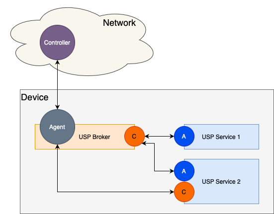
VI.4 USP Broker Responsibilities
A USP Broker generally has 3 main responsibilities:
- Track the Service Elements (portions of the data model) that the USP Services wish to expose to other entities.
- Proxy USP communications internally within the device based on the Service Elements that the USP Services have exposed.
- Provide a consolidated view of the device’s Service Elements to USP Controllers that reside externally to the device.
When a USP Service is started, there will be a data model registration to inform the USP Broker which Service Elements (portions of the data model) should be exposed for this USP Service. This means that one of the key responsibilities of the USP Broker is to track the portion of the data model associated with each USP Service, which is facilitated by receiving a Register USP message from the USP Agent of the USP Service. A subset of this key responsibility is to ensure that the USP Service is allowed to register the data model paths based on the permissions associated with the USP Service’s Agent.
The USP Agent portion of the USP Broker provides a consolidated view of the device’s Service Elements (including all Service Elements exposed by USP Services) to USP Controllers that are external to the device, and those USP Controllers will send USP messages to the device that require the USP Broker to proxy either the entire USP message or a portion of the USP message to one or more USP Services based on the Service Elements being exposed by the various USP Services. These USP messages can come in many forms:
- A Get message to retrieve various portions of the data model that could be distributed across multiple USP Services.
- A Set message to configure various portions of the data model that could be distributed across multiple USP Services.
- An Add message to create and configure a new instance of a data model object, and while each data model object is only served by a single USP Service, the Add message could be creating instances of multiple data model objects that could be distributed across multiple USP Services.
- A Delete message to remove an existing instance of a data model object, and while each data model object is only served by a single USP Service, the Delete message could be removing instances from multiple data model objects that could be distributed across multiple USP Services.
- An Operate message to execute a data model command, which would be handled by a single USP Service.
The USP Agent portion of the USP Broker might also need to handle notifications and subscriptions. These subscriptions might be created by either USP Controllers that are external to the device or USP Services that are internal to the device, where they are looking for notifications related to a part of the device’s Service Elements where some portions of that subscription could be distributed across multiple USP Services. This means that the USP Agent portion of the USP Broker might need to send USP Notify messages to external USP Controllers or internal USP Controllers associated with USP Services that have created associated Subscriptions.
VI.5 Data Model Implications for USP Brokers and USP Services
VI.5.1 UNIX Domain Socket Data Model Table and the UDS MTP Objects
The MTP table of the LocalAgent object represents the Message Transfer Protocols (MTPs) that a USP Agent is currently using. So an MTP instance with a Protocol of UNIX Domain Socket means that the USP Broker or USP Service has an Agent that is configured to use the UNIX Domain Socket MTP for communications within the device between the USP Broker and one or more USP Services.
Each instance of the LocalAgent.Controller table represents a USP Controller that has access to the associated USP Agent. For a USP Service that would be the USP Broker’s Controller, which means that a USP Service will only have 1 instance of the LocalAgent.Controller table and the UDS MTP object will contain a Reference to the UnixDomainSocket Object instance containing the Path to the Controller portion of the USP Broker and be in a Connect Mode. For a USP Broker that would be the USP Service’s Controller (if it exists), which means that a USP Broker will have an instance of the LocalAgent.Controller table for each USP Service that contains a Controller. Each LocalAgent.Controller instance would have a UDS MTP object that contains a reference to the USPService Object instance containing details about the USP Service itself.
The LocalAgent.MTP.UDS instance will be auto-created based on the USP Broker or USP Service supporting the UNIX Domain Socket MTP. The LocalAgent.Controller instances for a USP Broker and USP Services will be automatically created with the UDS instance based on USP Service startup procedures. Given that and the USP Broker has well-known paths for the Agent and Controller UNIX Domain Socket MTP, the UDS objects are read-only.
Due to the lack of a discovery mechanism and to ensure a interoperable environment where 3rd party USP Services can communicate with the USP Broker, it is highly recommended that the USP Broker’s secured (either via TLS or Password authentication)UNIX Domain Socket paths used for both its USP Agent and USP Controller be preset as follows:
- USP Broker’s USP Agent: /var/run/usp/broker_agent_path
- USP Broker’s USP Controller: /var/run/usp/broker_controller_path It is also conceivable that some solutions might choose to have other UNIX Domain Socket paths for internal use.
VI.5.2 USPServices.Trust Data Model Table
The USP Broker needs to validate which data model paths a USP Service is allowed to register. This information is tracked in the USPServcies.Trust table, which includes the following parameters:
- EndpointID: the Endpoint ID of the USP Agent within the USP Service
- Targets: a list of data model paths that the USP Service’s Agent is allowed to register
This table is populated as part of the processing of the
InstallDU() and Update() data model commands
based on the RegisterTrustPaths input argument. This table
can also be updated after the USP Service has been installed via a Set
message as the Parameters are writable.
When a USP Service disconnects then the associated USPServices.Trust table instance is not removed (it is persisted until the associated Software Module Deployment Unit is uninstalled).
If the USPServices.Trust table doesn’t contain an entry for an Endpoint ID of a USP Service’s Agent when it starts, then there are no permissions associated for that USP Service and it is not allowed to register any data model paths.
If the USPServices.Trust table has an entry for an Endpoint ID of a
USP Service’s Agent when it starts, but the TargetPaths
Parameter is empty then there are no permissions associated for that USP
Service and it is not allowed to register any data model paths.
VI.5.3 USPServices.USPService Data Model Table
The USP Broker should keep track of all USP Services it has an active connection to, which includes the following parameters:
- EndpointID: the Endpoint ID of the USP Agent within the USP Service
- DataModelPaths: a list of data model paths that have been registered by the USP Service
- DeploymentUnitRef: a reference to the Software Module Deployment Unit, if applicable
- HasController: a flag that indicates whether or not the USP Service has an embedded USP Controller (NOTE: this can be determined when the USP Service’s USP Controller connects to the USP Broker’s USP Agent if it is using the same Endpoint ID as the USP Service’s USP Agent)
When a USP Service disconnects then the associated USPServices.USPService table instance is removed.
VI.5.4 Example Data Models for a USP Broker and USP Services
Here’s an example set of data models for a USP Broker and 2 USP Services that matches the use cases depicted in the Figure shown in the previous section.
USP Broker (NOTE: there isn’t a Controller.1 instance because USP Service 1 doesn’t have a Controller):
UnixDomainSocket.1.Path = /var/run/usp/broker_agent_path
UnixDomainSocket.1.Mode = Listen
UnixDomainSocket.2.Path = /var/run/usp/broker_controller_path
UnixDomainSocket.2.Mode = Listen
LocalAgent.MTP.1.UDS.UnixDomainSocketRef = UnixDomainSocket.1
LocalAgent.Controller.2.MTP.1.UDS.UnixDomainSocketRef = UnixDomainSocket.1
LocalAgent.Controller.2.MTP.1.UDS.USPServiceRef = USPService.2
USPService.1.EndpointID = doc::Service1
USPService.1.DataModelPaths = PathA, PathB, PathC
USPService.1.DeploymentUnitRef = SoftwareModules.DeploymentUnit.1
USPService.1.HasController = false
USPService.2.EndpointID = doc::Service2
USPService.2.DataModelPaths = PathX, PathY, PathZ
USPService.2.DeploymentUnitRef = SoftwareModules.DeploymentUnit.2
USPService.2.HasController = true
USP Service 1 (NOTE: USP Service 1 doesn’t have a Controller, so there isn’t a Controller instance in the USP Broker for this USP Service):
UnixDomainSocket.2.Path = /var/run/usp/broker_controller_path
UnixDomainSocket.2.Mode = Connect
LocalAgent.MTP.1.UDS.UnixDomainSocketRef = UnixDomainSocket.2
LocalAgent.Controller.1.MTP.1.UDS.UnixDomainSocketRef = UnixDomainSocket.2
LocalAgent.Controller.1.MTP.1.UDS.USPServiceRef = <empty>
USP Service 2 (has both an Agent and a Controller):
UnixDomainSocket.1.Path = /var/run/usp/broker_agent_path
UnixDomainSocket.1.Mode = Connect
UnixDomainSocket.2.Path = /var/run/usp/broker_controller_path
UnixDomainSocket.2.Mode = Connect
LocalAgent.MTP.1.UDS.UnixDomainSocketRef = UnixDomainSocket.2
LocalAgent.Controller.1.MTP.1.UDS.UnixDomainSocketRef = UnixDomainSocket.2
LocalAgent.Controller.1.MTP.1.UDS.USPServiceRef = <empty>
VI.6 Startup and Shutdown Procedures
VI.6.1 Device Boot Procedures
When the device boots up, the USP Broker comes online. The USP Broker exposes both a USP Agent (communicating externally and internally; listening on a well-known internal path for communications via the Unix Domain Socket MTP) and an internal USP Controller (listening on a well-known internal path for communications via the Unix Domain Socket MTP). The USP Agent communicates externally via one or more of the USP defined MTPs (MQTT, STOMP, or WebSocket). The USP Agent also communicates internally via the Unix Domain Socket MTP and begins to listen on a well-known internal path. The USP Controller communicates internally via the Unix Domain Socket MTP and begins to listen on a well-known internal path. Each installed and enabled USP Service also starts up - see the next section.
VI.6.2 USP Service Startup Procedures
Use Case 1 - Data Model Provider Application:
As the USP Service starts up, it begins to connect to the USP Broker…
- The Agent within the USP Service initiates the UNIX Domain Socket
connection to the Controller on the USP Broker and the well-known
internal path
- Once the UNIX Domain Socket is connected, the USP Agent and USP Controller can perform TLS handshaking, if desired
- Once the UNIX Domain Socket is connected (and TLS handshaking is complete, if desired), the USP Service’s Agent will initiate the UNIX Domain Socket MTP Handshake mechanism
- Once the USP Broker’s Controller receives the UNIX Domain Socket MTP Handshake message, it will respond with its own Handshake message
- Once the UNIX Domain Socket MTP Handshake mechanism is successfully completed, the Agent within the USP Service sends an empty UnixDomainSocketConnectRecord
- After sending the empty UnixDomainSocketConnectRecord, the Agent within the USP Service sends a Register message to the Controller in the USP Broker that details the portion of the data model that is being exposed by the USP Service.
Use Case 2 - Integrated Data Model Application:
As the USP Service starts up, it begins to connect to the USP Broker…
- The Agent within the USP Service initiates the UNIX Domain Socket
connection to the Controller on the USP Broker and the well-known
internal path
- Once the UNIX Domain Socket is connected, the USP Agent and USP Controller can perform TLS handshaking, if desired
- Once the UNIX Domain Socket is connected (and TLS handshaking is complete, if desired), the USP Service’s Agent will initiate the UNIX Domain Socket MTP Handshake mechanism
- Once the USP Broker’s Controller receives the UNIX Domain Socket MTP Handshake message, it will respond with its own Handshake message
- Once the UNIX Domain Socket MTP Handshake mechanism is successfully completed, the Agent within the USP Service sends an empty UnixDomainSocketConnectRecord
- After sending the empty UnixDomainSocketConnectRecord, the Agent within the USP Service sends a Register message to the Controller in the USP Broker that details the portion of the data model that is being exposed by the USP Service.
- The Controller within the USP Service initiates the UNIX Domain
Socket connection to the Agent on the USP Broker and the well-known
internal path
- Once the UNIX Domain Socket is connected, the USP Service’s Controller will initiate the UNIX Domain Socket MTP Handshake mechanism
- Once the USP Broker’s Agent receives the UNIX Domain Socket MTP Handshake message, it will respond with its own Handshake message
- Once the UNIX Domain Socket MTP Handshake mechanism is successfully completed, the Agent within the USP Broker sends an empty UnixDomainSocketConnectRecord
- Once the USP Service identifies that it is connected to the USP Broker, the USP Service’s Controller can issue a GSDM to retrieve portions of the USP Broker’s supported data model that it might need to interact with
Use Case 3 - Cloud Application:
Note: One of the key tenets of USP was that multiple MTPs were defined not for general preferences but because each of them serves a different kind of use case. So when we define a new use case (like this one), it is certainly conceivable that some MTPs might not be appropriate. In this case, the WebSocket MTP is less appropriate, because it would require 2 socket connections to a WebSocket server.
As the USP Service starts up, it begins to connect to the USP Broker…
- The Cloud USP Service establishes a connection to the STOMP/MQTT
Broker based on the Agent’s data model (STOMP.Connection / MQTT.Client)
- The Agent within the Cloud USP Service send a STOMP/MQTT Connect Record to the Controller of the USP Broker
- After sending the appropriate Connect Record, the Agent within the USP Service sends a Register message to the Controller in the USP Broker that details the portion of the data model that is being exposed by the USP Service.
- The USP Broker establishes a connection to the STOMP/MQTT Broker
based on the Agent’s data model (STOMP.Connection / MQTT.Client)
- Note: The USP Controller will need to configure the USP Broker to communicate with the Cloud USP Service by setting up the associated MTP connection details.
- The Agent within the USP Broker sends a STOMP/MQTT Connect Record to
the Controller of the Cloud USP Service
- Note: This looks just like any other external USP Controller that is configured within the USP Broker’s Agent.
- Once the Controller within the Cloud USP Service receives the appropriate Connect Record, the Cloud USP Service’s Controller can issue a GSDM to retrieve portions of the USP Broker’s supported data model that it might need to interact with
VI.6.3 USP Service Shutdown Procedures
When a USP Service terminates (either gracefully by sending a Disconnect Record or abruptly by closing the UNIX Domain Socket connection), the USP Broker will remove the portion of the data model that was being exposed for the given USP Service.
VI.7 USP Services and Software Modules
USP Services have a rough correlation to Software Modules and the Software Module Management concepts defined within USP. This means that the installation of a Software Module might cause a USP Service to come into existence, and that the removal of a Software Module might cause a USP Service to cease to exist. That being said, not all Software Modules will contain a USP Service and not all USP Services will be part of a Software Module.
If the USP Service includes a Controller, its access to the data
model will be subject to the permissions described in Role Based Access Control (RBAC).
The Roles which the Service needs in order to function at all, and the
Roles which are not essential but would enable the Service to offer more
functionality, can be included in the InstallDU() command
using the RequiredRoles and OptionalRoles
arguments respectively; these arguments can also be included in the
Update() command if needed. The AvailableRoles
parameter of the Execution Environment into which the Service is being
installed lists the Roles which are available to Services according to
the security policy of the EE.
Note: Special care needs to be taken when processing requests to
create a new EE or to change the AvailableRoles of an
existing EE, for example to prevent a Controller from creating an EE
with Roles which it does not itself have and thereby enabling privilege
escalation.
Once the Controller has connected to the USP Broker, a reference to
the resulting instance of LocalAgent.Controller will be
exposed in parameter InternalController of the Deployment
Unit.
VI.7.1 Installing a Software Module
Installing a Software Module that contains a USP Service will cause the USP Service to startup (see VI.6.2) once the Software Module is installed and running.
VI.7.2 Updating a Software Module
Updating a Software Module that contains a USP Service will cause the USP Service to be stopped (see VI.6.3) and then restarted (see “USP Service Startup Procedures”) once the Software Module is updated and running once again.
VI.7.3 Deleting a Software Module
Deleting a Software Module that contains a USP Service will cause the USP Service to be removed (see VI.6.3).
This state machine diagram refers to the successful transitions caused by the USP commands that change the DU state and does not model the error cases.↩︎
This state machine diagram refers to the successful transitions caused by the
SetRequestedState()or theRestart()command within theExecutionUnittable and does not model the error cases.↩︎